


Troubleshooting
22
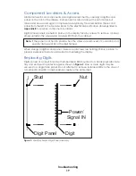
Radio Interference
If it has been determined that a nearby display’s radio signal is interfering, the settings of
the radio receiver or wireless base station inside the display(s) must be changed.
1�
To locate the radio receiver or base
station, simply look for the black antenna
sticking out the front of the display.
2�
Open the access panel to which the
receiver is attached as described in
Component Locations & Access (p�19)
.
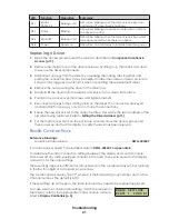
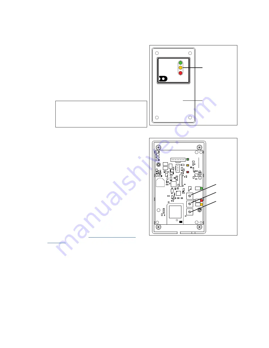
3�
The radio receiver has a plastic cover
with a window to view status indicators
(
Note:
While it is necessary for the display
to be powered on to check the
indicators, always disconnect
power before servicing.
4�
Remove the four screws in each corner
using a #2 Philips screwdriver and lift off
the cover.
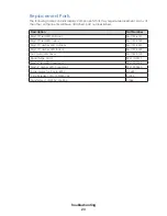
5�
Use a small flathead screwdriver to set
the CHAN and BCAST switches to a new
channel and broadcast group (1-8) as
needed. Be sure to always leave FUNC set
6�
Screw the cover back on and securely
close the access panel.
7�
Enter the correct sport code and new
radio settings into the console to test the
radio control. Refer to the appropriate
control console manual listed in
.
For more information, refer to the
Gen VI
Radio Installation Manual (DD2362277)
,
available online at
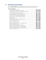
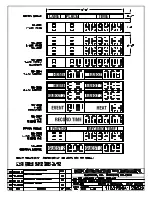
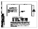
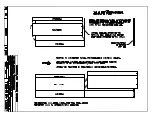
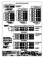
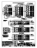
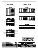
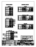
Schematics
For advanced troubleshooting and repair, it may be necessary to consult the schematic
drawings. Listed in
Appendix B
, schematic drawings show detailed power and signal
wiring diagrams of internal display components such as drivers, horn interface cards, and
transformers as well as optional components like radio receivers.
2.4GHZ
LL-2567
REV 01
POWER
RADIO IN RANGE
DATA OUT
DAKTRONICS
WIRELESS RECEIVER
Status Indicators
Remove Cover to
Access Switches
Figure 11:
Radio Receiver w/ Cover
FUNC
CHAN
BCAST
X1
X2
J4
0
0
0
1
1
1
CHAN
GEN V
GEN VI
BCAST
CHAN
FUNC
BCAST setting at any time
BCAST 1
BCAST 2
BCAST 3
BCAST 4
Figure 12:
Radio Receiver Switches
Содержание SW-2001
Страница 30: ...This page intentionally left blank ...
Страница 32: ...This page intentionally left blank ...
Страница 33: ......
Страница 34: ......
Страница 35: ......
Страница 36: ......
Страница 37: ......
Страница 38: ......
Страница 39: ......
Страница 40: ......
Страница 41: ......
Страница 42: ......
Страница 43: ......
Страница 44: ......
Страница 45: ......
Страница 46: ......
Страница 47: ......
Страница 48: ......
Страница 49: ......
Страница 50: ......
Страница 51: ......
Страница 52: ......
Страница 53: ......
Страница 54: ...This page intentionally left blank ...
Страница 56: ...This page intentionally left blank ...
Страница 57: ......
Страница 58: ......
Страница 60: ......
Страница 61: ......
Страница 63: ......
Страница 64: ......
Страница 65: ......
Страница 66: ......
Страница 67: ......
Страница 68: ......
Страница 69: ......
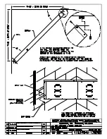
Страница 72: ...AH LED AQUATICS SCOREBOARD INTERNAL CABLE ROUTING A VANBEMMEL 11 APR 00 P1153 R 10 A 1 20 130679 03 ...
Страница 74: ......
Страница 75: ......
Страница 77: ......
Страница 78: ...DATE REV BY DATE REV BY HORN 2 3 4 1 DATE REV BY 03 3 MAR 15 KCS UPDATED WITH GYRUS AND ADAPTOR HARNESS VIEWS ...
Страница 82: ...This page intentionally left blank ...
Страница 84: ...This page intentionally left blank ...
Страница 88: ...This page intentionally left blank ...


