Electrical Installation
12
Indoor Signal Connection
Wired signal installation requires routing control cable from the control console to a signal
junction box (J-box) near the display. At a minimum, use a paired, 22 AWG shielded
cable (Daktronics part # W-1077).
1�
Route signal cable in conduit from the display location to a signal junction box
(J-box) or wall plate near the control location.
2�
Install the 1/4” phone plug (part # 0L-40683) to the display end of the cable.
3�
Insert the plug into the
SIGNAL IN
jack located on the left side of the display.
Note:
If the signal jack is not already installed, refer to
4�
Connect a signal cable from the J-box or wall plate on the control console end to
the
J1
,
J2
, or
J3
jack on the back of the OmniSport 2000 console.
• If using a Main Clock Start/Stop Switch (part # 0A-1166-0003), connect it to the
J8
jack on the OmniSport 2000 console.
• If using a Shot Clock Start/Stop Switch (part # 0A-1196-0031), connect it to the
J9
jack on the OmniSport 2000 console.
Outdoor Signal Connection
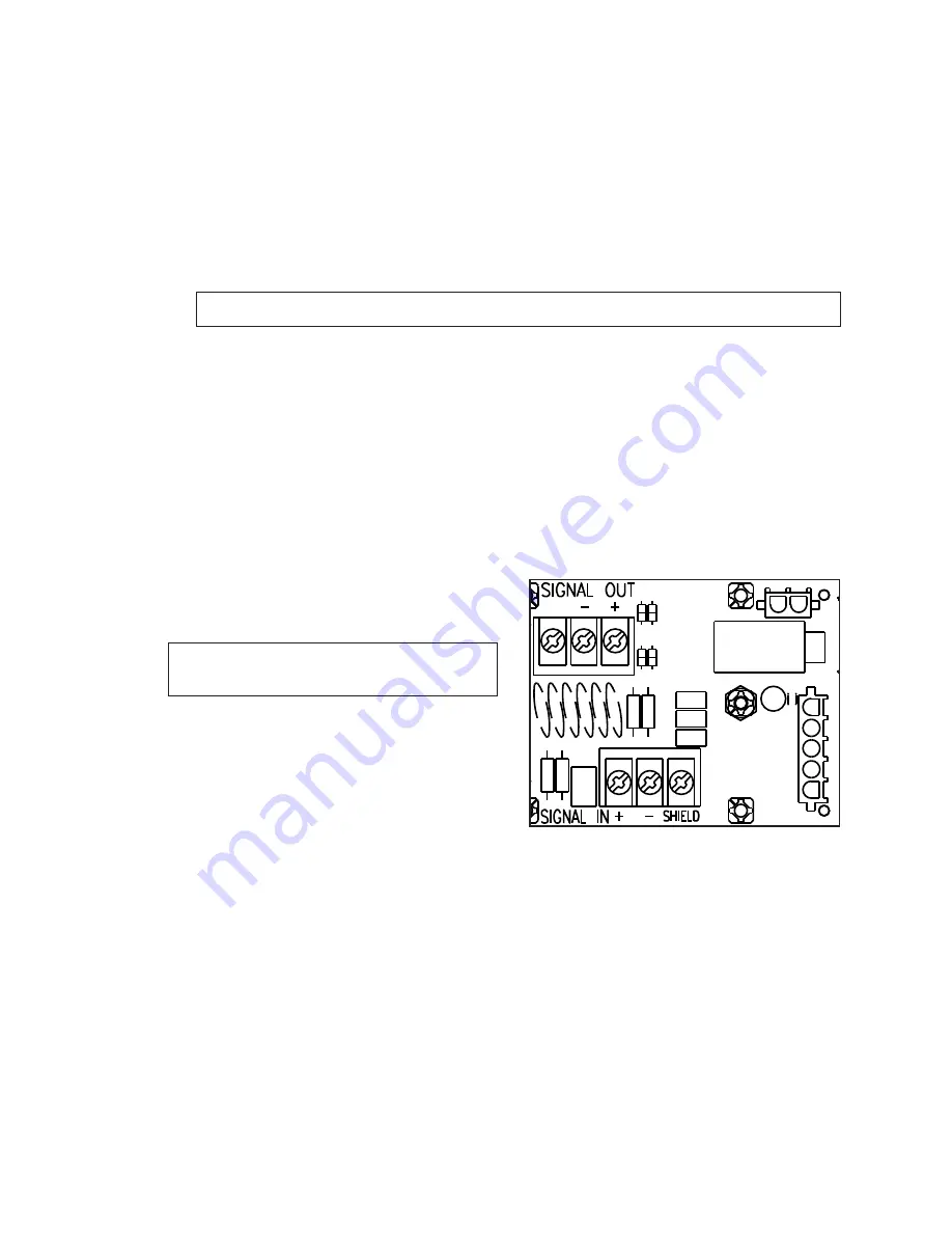
Route copper signal cable through the conduit knockout on the rear of the display to
the signal surge arrestor card (
), located in the load center.
At the
SIGNAL IN
terminal block, connect red
signal wire to positive (+) and black signal
wire to negative (–).
Note:
Ensure shield (silver) wire is properly
connected to the
SHIELD
terminal.
At a minimum, single-pair, shielded cable, 22
AWG (part # W-1077) is recommended.
Install an indoor or outdoor 1/4" J-box as
needed at the control location, and connect
a signal cable from the J-box on the control
console end to the
J1
,
J2
, or
J3
jack on the
back of the OmniSport 2000 console.
• If using a Main Clock Start/Stop Switch (part # 0A-1166-0003), connect it to the
J8
jack on the OmniSport 2000 console.
• If using a Shot Clock Start/Stop Switch (part # 0A-1196-0031), connect it to the
J9
jack on the OmniSport 2000 console.
BLK
WHT
GND
Figure 7:
Signal Surge Arrester Card
Содержание SW-2001
Страница 30: ...This page intentionally left blank ...
Страница 32: ...This page intentionally left blank ...
Страница 33: ......
Страница 34: ......
Страница 35: ......
Страница 36: ......
Страница 37: ......
Страница 38: ......
Страница 39: ......
Страница 40: ......
Страница 41: ......
Страница 42: ......
Страница 43: ......
Страница 44: ......
Страница 45: ......
Страница 46: ......
Страница 47: ......
Страница 48: ......
Страница 49: ......
Страница 50: ......
Страница 51: ......
Страница 52: ......
Страница 53: ......
Страница 54: ...This page intentionally left blank ...
Страница 56: ...This page intentionally left blank ...
Страница 57: ......
Страница 58: ......
Страница 60: ......
Страница 61: ......
Страница 63: ......
Страница 64: ......
Страница 65: ......
Страница 66: ......
Страница 67: ......
Страница 68: ......
Страница 69: ......
Страница 72: ...AH LED AQUATICS SCOREBOARD INTERNAL CABLE ROUTING A VANBEMMEL 11 APR 00 P1153 R 10 A 1 20 130679 03 ...
Страница 74: ......
Страница 75: ......
Страница 77: ......
Страница 78: ...DATE REV BY DATE REV BY HORN 2 3 4 1 DATE REV BY 03 3 MAR 15 KCS UPDATED WITH GYRUS AND ADAPTOR HARNESS VIEWS ...
Страница 82: ...This page intentionally left blank ...
Страница 84: ...This page intentionally left blank ...
Страница 88: ...This page intentionally left blank ...


