

Introduction
2
Project-specific information takes precedence over any other general information found
in this manual. Such information may include:
•
Schematic Drawings:
describe internal power and signal wiring
•
Shop Drawings:
describe mounting methods to structural elements, access method
(front or rear), and power and signal entrance points
•
System Riser Diagrams:
describe power and signal connections between system
components and the control location; may also include control room layout and
schematic
•
Final Assembly Drawings:
describe internal component locations and detailed
product appearance with part numbers and quantities
Ensure all applicable material has been gathered before beginning the installation.
Contact a Daktronics sales coordinator or project manager.
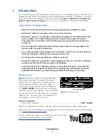
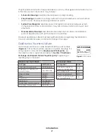
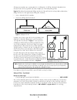
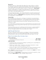
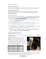
Daktronics Nomenclature
Most components have a white label that lists the part number
(
). Part numbers will also appear on certain drawings. If a
component is not found in the
the label to order a replacement. Refer to
Exchange and Repair & Return Programs (p�26)
repairing any component.
Main Component Labels
Part Type
Part Number
Individual circuit board
0P-XXXX-XXXX
Assembly; a collection of
circuit boards
0A-XXXX-XXXX
Wire or cable
W-XXXX
Fuse
F-XXXX
Transformer
T-XXXX
Metal part
0M-XXXXXXX
Fabricated metal assembly
0S-XXXXXX
Specially ordered part
PR-XXXXX-X
0P-1127-0024
SN:
2465
02/19/12 Rev. 1
Figure 2:
Part Label
Accessory Labels
Component
Label
Termination block for
power or signal cable
TBXX
Grounding point
EXX
Power or signal jack
JXX
Power or signal plug for
the opposite jack
PXX
Содержание SPORTSOUND 1500HD
Страница 32: ...This page intentionally left blank ...
Страница 34: ...This page intentionally left blank ...
Страница 38: ...This page intentionally left blank ...
Страница 42: ......
Страница 43: ......
Страница 46: ...This page intentionally left blank ...
Страница 48: ...This page intentionally left blank ...
Страница 50: ...This page intentionally left blank ...
Страница 54: ...This page intentionally left blank ...


