


Venus Software Configuration
13
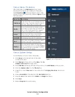
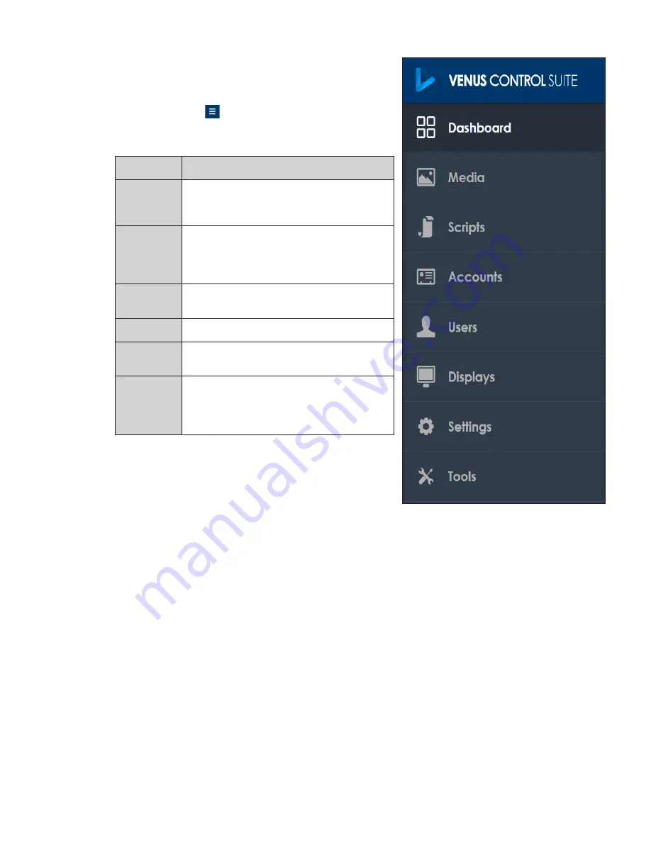
Venus Menu Overview
After initial login, the
Dashboard
window opens
showing status tiles for each display in the system.
Click
Show Menu
at the upper-left corner of the
screen to open the main menu. Refer to
and
the table below.
Menu Item Description
Dashboard
Shows status tiles for each display and any
active, online, associated devices such as
VIP-5X60s, DMP-8000s, and DMP-5000s
Media
Opens the Media Library where content
media files are uploaded, created through
the Content Studio application, tagged,
stored, and assigned to an account
Scripts
Opens the Script Library where display
commands are created and stored
Accounts
Creates new accounts for advertisers
Users
Lists current user profiles and allows users to
update passwords or add new users
Displays
Lists all available displays and provides
basic management tools including
Devices
for linking DMP-8000s, DMP-5000s, and VIP-
5X60s to a specific display
Venus System Setup
To add displays to Venus, follow these step
s:
1�
Click
Menu
on the top-left side of the initial
dashboard screen.
2�
Click
Displays
at the bottom of the
Menu
. The
No
displays were found
message opens.
3�
Click
Add New
at the top-left side of the window. The
Add Display
window opens.
4�
Enter the
display name
into the
Title text
box.
5�
Select the correct
time zone
for the display from the
Display Time Zone
drop-down
menu.
6�
Enter a
description
of the display in the
Description
text box.
7�
Enter the
size
of the display in the
Width
and
Height
text boxes.
8�
Click
Save
.
9�
Repeat
Steps 3-8
for each display.
Figure 11:
Venus
®
Main Menu
Содержание Large Matrix Galaxy GT6X Series
Страница 4: ...This page intentionally left blank...
Страница 30: ...This page intentionally left blank...
Страница 32: ...Daktronics Warranty and Limitation of Liability 28...


