background image

Maintenance and Troubleshooting

42

9  Maintenance and Troubleshooting

Important Notes:

•  Visit Daktronics Support videos at 

www.youtube.com/daktronicssupport

.

•  Disconnect power before any repair or maintenance work is done on the display.
• 

Qualified service personnel must make any access to internal display electronics.

•  Disconnect power when the display is not in use. Leaving power on for prolonged 

periods of time shortens the life of some electronic components.

Visual Structural Inspection

At least once a year: 

•  Check the display to ensure the structure and 

components are in good condition. 

•  Inspect the paint and cabinet for corrosion. 
•  Make sure fasteners are tight; tighten or 

replace as required. 

Display Diagnostics

Driver Diagnostic LEDs

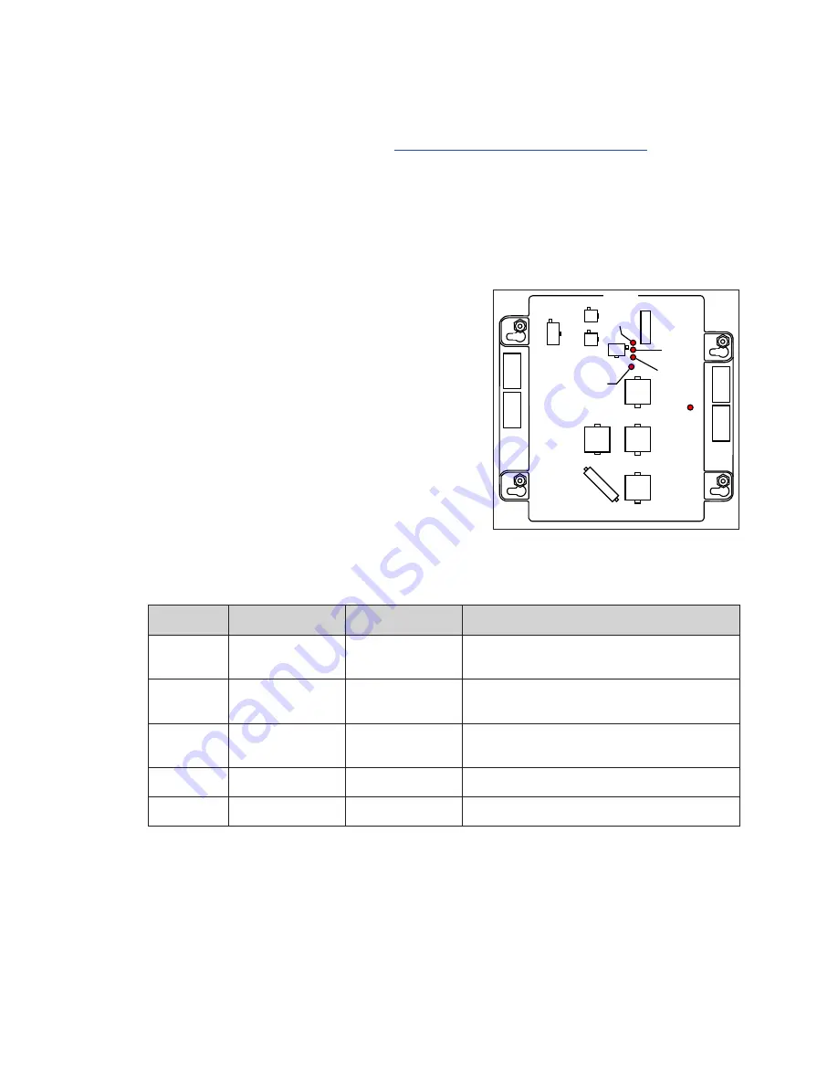
The driver has five LEDs that indicate whether it is 

functioning properly. Refer to 

Figure 66

 for their 

locations. These LEDs can help pinpoint problems 

with driver setup or operation.

The following table provides a key to what the diagnostic LEDs indicate:

LED Name Function

Label

Indication

DS1

Status

Comm Port Status Blinks when communication is detected.

Off when no communication is detected.

DS2

Status – J10 Status Line to Line

On when connected.

Off when disconnected.

DS3

Status – J9 Status

Line to Line

On when connected.

Off when disconnected.

DS4

Driver Status

Heartbeat

Blinks once per second when OK.

DS7

Power

Power

On when receiving power.

POWER IN

24 DC

J14

DIGIT 4

J13

DIGIT 3

J12

DIGIT 2

J15

DECIMAL

J11

DIGIT 1

J18

J10

J9

J16

DS7

POWER

ON = GOOD

DS4 HEARTBEAT

1 SEC. BLINK = OK

DS3 (J9)*

DS2 (J10)*

LINE TO

LINE

DS1 (J16)

COMM

PORT

STATUS

LINE

TO

LINE

CASH/

CREDIT

COMM

PORT

J3

Figure 66: 

Driver Diagnostic LED Locations

Содержание FUELIGHT FL-3000 Series

Страница 1: ...ve Brookings SD 57006 5128 www daktronics com support 800 325 8766 FUELIGHTTM FL 3000 FL 4500 SERIES PETROLEUM PRICE DISPLAY CASH CREDIT DISPLAY INSTALLATION OPERATION MANUAL P1611 P1805 DD2238839 Rev 30 24 February 2022 ...

Страница 2: ... that may cause undesired operation Warning Risk of fire or electric shock LED Retrofit Kit installation requires knowledge of sign electrical systems If not qualified do not attempt installation Contact a qualified electrician Warning Risk of fire or electric shock Install this kit only in host signs that have been identified in the installation instructions and where the input rating of the retr...

Страница 3: ...3 1500 Connection 15 General Radio Setup 15 Server Radio Installation 16 Client Radio Installation 17 Outdoor J box Installation 17 FLD3 2000 Connection 18 Indoor J box Installation 18 Outdoor J box Installation 19 Limitation of Liability 19 FLXR3 Server Radio Kit 20 Indoor Server Radio Installation 20 Mount the Exterior Server Radio Antenna 20 Client Radio Installation 21 FLXR3 Client Radio Set U...

Страница 4: ...est Patterns 38 Communication Diagnostics 38 About 40 Dimming 40 Update the Display 41 9 Maintenance and Troubleshooting 42 Visual Structural Inspection 42 Display Diagnostics 42 Driver Diagnostic LEDs 42 Display Troubleshooting 43 Multi Pylon Troubleshooting Steps 44 10 Replacement Parts 45 Digit Segment Layout 45 11 Daktronics Exchange and Repair Return Programs 46 Exchange Program 46 Repair Ret...

Страница 5: ...dix B Daktronics Warranty and Limitation of Liability p 51 for Daktronics Warranty and Limitation of Liability information Display Overview Fuelight model numbers FL 3000 U S FL 4500 International are defined as follows FL 3000 HH R DI or FL 4500 HH R DI FL 3000 or FL 4500 Fuelight Product Series HH Digit Height in Inches R A G Color R Red A Amber G Green DI Drop In Note The model number is listed...

Страница 6: ...ht displays are controlled using one of the following communication kits FLR3 100 includes an RC 50 key fob remote FLR3 1500 includes a DM 100 controller and fixed mount radio or FLD3 2000 DM 100 controller A typical display system is shown in Figure 3 Safety Precautions Please read and understand installation instructions before installing Do not disassemble control equipment or electronic compon...

Страница 7: ...etroleum Price digit displays are front ventilated The display must NOT be fully enclosed inside a support structure or sign or behind a sign face of plastic glass or other material The front of the display must be exposed to the air to allow for convection cooling Fuelight displays are designed to operate in ambient temperatures ranging from 40 F to 120 F 40 C to 49 C However overall sign structu...

Страница 8: ...o the structure using appropriate hardware for site conditions Refer to Figure 5 Actual site demands will dictate variances and appropriate mounting methods 6 Repair and seal any unused openings in the sign structure Note Openings greater than 1 2 13 mm in diameter require a metal patch secured by screws or rivets and caulked with non hardening caulk Smaller openings may be sealed with non hardeni...

Страница 9: ...and termination at the display Daktronics engineering staff must approve all proposed changes or the warranty will be void Improper installation could result in serious damage to the equipment and could be hazardous to personnel Size conductors of circuits delivering power to a Daktronics display according to local and national electrical codes so that the power distribution systems can deliver fu...

Страница 10: ...locations vary between display sizes Refer to Figure 6 for approximate component locations TOP TOP TOP TOP Slotted Latch Slotted Latch Grounding Stud Driver Power Supply Knockouts Model Number Label Figure 6 Internal Component Locations Grounding FL 3000 and FL 4500 series displays do not require a local earth ground electrode The displays are designed so the most sensitive components are isolated...

Страница 11: ...ple Fuelight Displays To connect power to the display follow these steps 1 Route the power cable into the display through one of the knockouts on the display s backsheet Refer to Figure 7 2 Use wire nuts or other appropriate hardware to connect power wires hot black and neutral white to the power supply harness or pigtail Refer to Figure 7 and Figure 8 3 Connect power supply ground wire to the gro...

Страница 12: ...8 Power Out to Cash Credit Display Interconnect Wiring Signal travels from the host driver jack J9 to additional display drivers through the Line to Line cable Line to line connections are made using jacks J9 and J10 on the driver The preferred cable routing has signal leaving each driver from jack J9 and entering the next driver on jack J10 Each time you connect the line to line cable to J9 you m...

Страница 13: ...vided cable bushings that snap into place 6 Repeat until all displays are connected Note Do not connect the last display driver back to the host Important Notes Route cables at least 6 152 mm away from interfering sources like ballasts florescent light bulbs power sources any type of motor etc Pull excess cable into the display cabinet coil cable zip tie it together and carefully place coil inside...

Страница 14: ...ies H Modules High W Modules Wide R G Color R Red G Green DI Drop In Note Find the model number on a label located inside the display Refer to Figure 14 The Cash Credit series includes the following standard sizes 1 1H x 1W refer to Figure 15 2 2H x 2W refer to Figure 16 3 Alternate Size 1H x 2W refer to Figure 17 4 Alternate Size 2H x 1W refer to Figure 18 A typical display system is shown in Fig...

Страница 15: ...te conditions Refer to Figure 23 Actual site demands will dictate variances and appropriate mounting methods Figure 23 Secure Display in Sign Structure 5 Repair and seal any unused openings in the sign structure Note Openings greater than 1 2 12 7 mm in diameter require a metal patch secured by screws or rivets and caulked with non hardening caulk Smaller openings may be sealed with non hardening ...

Страница 16: ...t so that all ungrounded conductors can be disconnected To connect power to the display follow these steps 1 Route power cable into the display through one of the knockouts on the display s backsheet 2 Use wire nuts or other appropriate hardware to connect power wires hot black and neutral white to the power supply harness or pigtail Refer to Figure 25 3 Connect supply power ground wire to the gro...

Страница 17: ... maximum range of 100 30 5 m FLR3 400 kits have a maximum range of 400 122 m Install the Receiver 1 Using a flat head screwdriver open the digit face to access inside the digit cabinet 2 Remove both antenna hole plugs from the digit face Refer to Figure 28 3 Place the receiver on to the mounting studs on the back of the digit face Refer to Figure 29 4 Use a 5 16 nut driver to secure the receiver t...

Страница 18: ...ver Pair Key Fob with Display To pair the FLR3 100 400 key fob with the radio receiver in the display follow these steps Note If these steps are not completed the display will not recognize or respond to the key fob 1 Turn power on to the display 2 While display is booting up or within five minutes press and hold the LINE 1 plus and minus buttons until the decimal flashes three times The display s...

Страница 19: ...ics Customer Service Exx All other error codes relate to the display driver Contact Daktronics for more information or to order a new driver After the self test each display is programmed with a default price that corresponds to the line number for which it is addressed Changing each line s price overwrites these defaults FLR3 1500 and FLD3 2000 Outdoor Indoor Control Kits The Fuelight Fuelink 3 C...

Страница 20: ...io The maximum distance from the J box to the server radio is 1000 305 m c At the server radio connect the wires to the terminal plug labeled TB2 RS 422 IN The cable is pinned one to one Refer to the table J Box Wire Server Radio POWER Green VDC P 422 RX P Blue D1OUT P 422 RX N White D1OUT N 422 TX P Brown D1IN P 422 TX N Black D1IN N GND Red GND N d Plug the handheld controller serial cable into ...

Страница 21: ... shown in Figure 35 securely on the support pole so it is easily accessible for plugging in the handheld controller Mounting tabs may be attached to the back of the J box with provided screws 2 Orient the box so the quick connect cable runs out the bottom of the box 3 Connect the unterminated end of the quick connect cable inside the outdoor J box according to the table below Outdoor J box Termina...

Страница 22: ...igure 36 A label inside the J box illustrated in Figure 37 shows connection information Indoor J box Terminal Wire Color Surge Card TB2 Terminal Number TB2 4 Black TX TB2 3 Red TX TB2 2 Green RX TB2 1 White RX 4 Run the cable from Step 3 above through conduit from the indoor J box to the outdoor J box Connect the cable in the outdoor J box to TB1 on input card Outdoor J box Terminal Wire Color Sur...

Страница 23: ...e pylon connect the master driver to the quick connect cable on the input card and the last driver to the quick connect cable connected to TB3 of the output driver 5 Mount the bulkhead connector to the display structure within 8 2 4 m of any display driver 6 Plug the terminated end of the quick connect cable into jack J16 on a driver Outdoor J box Terminal Wire Color TB3 4 Black TB3 3 White TB3 2 ...

Страница 24: ...ransformer B 2 Feed the interconnect cable H between server radio E and DM 100 I Connect the wall pack transformer B to the server radio E Mount the Exterior Server Radio Antenna 1 Mount the high gain antenna G using mounting hardware A on the outside of the building that contains the server radio Mount the antenna as high as possible in free air Locate the antenna within 50 15 2 m of the server r...

Страница 25: ...the 10 3 m bulkhead routed to the exterior 3 Mount the client radio box within the inside of the Fuelight display Refer to Figure 45 4 Mount the antenna in an optimal location as shown in Figure 46 that is elevated farther off the ground has improved line of sight to the server radio antenna and within 10 3 m of the client radio Daktronics provides a 10 3 m antenna extension cable to allow for opt...

Страница 26: ...nds After five seconds the LCD shows NET Y where Y represents the current network number Note A Network Number is a unique channel for each installation site and prevents networks located close to one another from interfering with each other For example if two installations are across the street from one another one site could be set to network 1 and the other site set to network 2 5 Press the res...

Страница 27: ...rver radio through a web interface attach an Ethernet cable from the radio to a computer and follow these steps 1 Configure the computer s IP address for the same subnet as the radio s IP Open a web browser and navigate to the radio s IP address example http 192 168 0 30 2 Enter the radio password to gain access to the advanced diagnostics and configuration The default password is password Figure ...

Страница 28: ...6 Figure 57 shows what the server radio displays once one or more client radios are detected and connected The bars show the signal strength received from the client radios When more than one client radio is connected this is an average value The number shown below the signal strength bars is a Quality of Service percentage the percent of data successfully exchanged between server and client radio...

Страница 29: ...ind any client radios with which to connect A client radio resets every 30 seconds if it does not find a server radio with which to connect The auto reset feature is disabled when there is a connection on the Ethernet port when connected with a computer On initial setup it may take a few reset cycles for all the radios to find each other and the Quality of Service number may take a few minutes to ...

Страница 30: ...seconds until the displays show prices and they no longer flash Note All displays are programmed with a default price matching their line number Use this to identify that all displays are addressed correctly Configure Numbers To configure the numbers six and nine as well as the fraction display preferences follow these steps 1 Make sure all price displays are powered on 2 Press and hold the LINE 3...

Страница 31: ...atic Dimming Mode 1 Press and hold the LINE 1 minus and LINE 4 plus buttons to enter Configuration Mode 2 Press the LINE 1 plus and minus buttons to switch from Automatic Dimming to Manual Dimming Set is shown on the display when in Manual Dimming Mode Aut is shown on the display when in Automatic Dimming Mode 3 Press the LINE 2 plus and minus buttons to adjust the brightness of manual dimming mod...

Страница 32: ...Cash Credit Displays 1 Press and hold any key fob button for 5 seconds until the decimal flashes and the display is in edit mode 2 When the Cash Credit display shows its first price state use the plus and minus buttons on the line you are editing to revise the price Note 5 is the starting price when prices are set for the first time 3 Wait 10 seconds until the Cash Credit display shows the second ...

Страница 33: ...Terms Host Display Display that has the receiver card connected to it Fuelight System Host display and all other displays that are connected to the host with a line to line cable Option 1 Dedicated Branch Circuits 1 Ensure a dedicated branch circuit is installed for each Fuelight system This allows a power cycle for each system so the key fob can be synced only to that system 2 Shut off all power ...

Страница 34: ...4 4 After the first Fuelight system and key fob are synced disconnect the power supply from the driver after 5 minutes 5 Power up the second Fuelight system by reconnecting the power supply to the driver and sync that key fob 6 Unplug the power supply from the driver after 5 minutes 7 Repeat this step for additional Fuelight systems 8 Once all key fobs are synced and marked to designate which Fuel...

Страница 35: ... line of the LCD during startup press the SET FUNCTION key while the second LCD prompt is displayed SELECT FUNCTION GAS PRICE Press the Up and Down Arrow keys until the GAS PRICE option is shown and then press ENTER to accept FL 4500 Rate Display Setup Set international displays to the rate display function which should position the decimal point in the correct position Instructions are provided b...

Страница 36: ... FILE RESULTS X NETWORKS FOUND NETWORK X OF X DETECTING DISPLAYS DETECTED SIGN X LX SENDING CONFIGURATION Only shown when FLR3 1500 communication is used Shown when either FLR3 1500 or FLD3 2000 communication is used The controller discovers each network and detects its displays before moving on to the next network This process may take a few minutes Menu Options 1 Press the MENU key 2 Press the U...

Страница 37: ... the example the active price states Cash Credit and Debit are used State 1 Cash Default State 2 Credit State 3 Debit Price State Number State 1 State 2 State 3 1 2 1 2 3 1 3 2 3 1 2 3 Standard content shown Custom content is available and will vary from what appears above When in configuration mode numbers that represent selected active price states are shown on the DM 100 screen Display Menu LCD...

Страница 38: ... key to map lines in the next network Continue pressing the CLEAR SET FUNCTION button to exit to the main screen CONFIGURATION STYLE SELECT STYLE NO TAILS 9 10 SELECT STYLE TAILS 9 10 SELECT STYLE NO TAILS 9 SELECT STYLE TAILS 9 Press ENTER to change the appearance of numbers six and nine 6 and 9 Figure 65 shows examples Note For Domestic displays with a 9 10 digit the number 3 must show in the fi...

Страница 39: ...ss the MENU key 2 Press the Down Arrow key to POS SETTINGS and then press ENTER 3 Press the Down Arrow key to GENERIC and then press ENTER Line 1 Product enter 1 and then press ENTER Gas Price Line 2 Product enter 2 and then press ENTER Diesel Price Line 3 Product None press ENTER Line 4 Product None press ENTER Line 5 Product None press ENTER Enter Line 1 discount offsets for all three Line 1 Sta...

Страница 40: ... lost connection enter prices manually into the DM 100 When entering fuel prices manually on the main menu POS OVERRIDE appears after an attempt to edit prices on the DM 100 if it is configured for PoS control Press ENTER and enter the price using the keypad With manual price entry on the DM 100 keypad the price for each CASH CREDIT and DEBIT state for each fuel grade is entered Offsets do not app...

Страница 41: ...1 DEVICE WIRED DETECTED Press ENTER to get display status Press the Down Arrow key to move to another sign and line number Press ENTER to view Display Status menu items Driver Firmware Version Dim Level Dimming Mode Automatic or Manual Light Sensor Status Com1 Device Detection Detect Displays 1 Press the MENU key followed by ENTER to select the Diagnostics Menu 2 Press the Down Arrow key to reach ...

Страница 42: ... number A XX where XX is the hardware address d X where X is the dimming mode A for automatic F for fixed or manual dimming t XX where XX is the internal sign temperature in C Press the Down Arrow key to move to the next test pattern Press ENTER to start the CYCLE NUMS test pattern Each digit will display numbers 0 9 in sequence Press CLEAR at any time to exit the test pattern menu Communication D...

Страница 43: ... DIAGNOSTICS COM PORT TESTS SELECT TEST RS232 COM0 SELECT TEST RS232 COM0 COM1 SELECT TEST RS232 COM1 SELECT TEST CURRENT LOOP Press ENTER to test the operation of the DM 100 COM ports and or cables These tests are useful for determining if the ports themselves are operational and if cables are good Press the Up and Down Arrow keys to select the appropriate test and then press ENTER RS232 COM0 Che...

Страница 44: ...tness accordingly Manual Dimming retains the same LED brightness level regardless of the level of light detected at the display 2 Refer to the following tables to set the dimming level LCD Screen Action Information Shown DIMMING AUTOMATIC DIMMING MANUAL DIMMING BLANK SIGN Press the Down Arrow key to toggle through dimming settings Automatic The display automatically dims based on the light detecte...

Страница 45: ...ed the display illuminates in full bright mode which is the maximum intensity level When BLANK SIGN is selected the following prompt appears LCD Screen Action Information Shown BLANK THE SIGN ENT YES BLANK THE SIGN CLR NO Press ENTER to blank the sign Press CLEAR to leave the sign on When in Blank Mode the digits on all of the displays will turn off and only the decimal will be lit RESTART SIGN EN...

Страница 46: ...nostic LEDs The driver has five LEDs that indicate whether it is functioning properly Refer to Figure 66 for their locations These LEDs can help pinpoint problems with driver setup or operation The following table provides a key to what the diagnostic LEDs indicate LED Name Function Label Indication DS1 Status Comm Port Status Blinks when communication is detected Off when no communication is dete...

Страница 47: ...r each display on each face Refer to Map Line Numbers p 26 and Configuration p 34 along with the communications quick guides to set correct display address Garbled display Driver malfunction Check driver to make sure signal cables are routed to the correct digits Cycle power to the display Replace the driver Digit malfunction Replace the digit Digit will not light Cable to the digit broken or disc...

Страница 48: ...lays are detected 10 Verify all displays and lines are detected 11 Manually send the current prices to the display s from the DM 100 12 Verify that the DM 100 states Sequence Sent then Display Response Use the following as a guide for some Point of Sales Systems e g Radiant 1 Verify the ICON on the PoS register does not say Price sign is off line if it does connect the PoS to the DM 100 2 Manually...

Страница 49: ...wn in Figure 67 Part numbers may also appear on illustrations and reference drawings as well as in the Bill of Materials BOM for the project If a replacement part cannot be identified contact Daktronics Customer Service Refer to Section 11 Daktronics Exchange and Repair Return Programs p 46 if replacing or repairing any display component Digit Segment Layout When ordering replacement segments for ...

Страница 50: ...1040 2 When the new exchange part is received mail the old part to Daktronics If the replacement part fixes the problem send in the problem part being replaced a Package the old part in the same shipping materials in which the replacement part arrived b Fill out and attach the enclosed UPS shipping document c Ship the part to Daktronics 3 A charge will be made for the replacement part immediately ...

Страница 51: ...ent damage during shipment Electronic components such as printed circuit boards should be placed in an antistatic bag before boxing Daktronics does not recommend using packing peanuts when shipping 4 Enclose Name Address Phone number RMA number A clear description of symptoms Shipping Address Daktronics Customer Service 600 E 54th St N Case ____________ Sioux Falls SD 57104 Attn RMA __________ Dak...

Страница 52: ...This page intentionally left blank ...

Страница 53: ...177644 Shop Drawing FL 3000 24 DI DWG 01086412 Shop Drawing FL 3000 30 DI DWG 01086413 Shop Drawing FL 4500 8 DI DWG 01086414 Shop Drawing FL 4500 12 DI DWG 01086415 Shop Drawing FL 4500 16 DI DWG 01086419 Shop Drawing FL 4500 18 DI DWG 01086420 Shop Drawing FL 4500 24 DI DWG 01086421 Shop Drawing FL 4500 30 DI DWG 01086422 Shop Drawing CC1 1H1W DI DWG 01162030 Shop Drawing CC1 1H2W DI DWG 0116203...

Страница 54: ...This page intentionally left blank ...

Страница 55: ...Daktronics Warranty and Limitation of Liability 51 B Daktronics Warranty and Limitation of Liability This section includes the Daktronics Warranty Limitation of Liability statement SL 02374 ...

Страница 56: ...This page intentionally left blank ...

Страница 57: ...ty per Incoterms 2020 otherwise End User shall pay transportation charges to return the Equipment back to the End User and such Equipment shall be shipped Ex Works Daktronics designated facility per Incoterms 2020 All returns must be pre approved by Daktronics before shipment Daktronics shall not be obligated to pay freight for any unapproved return End User shall pay any upgraded or expedited tra...

Страница 58: ... Daktronics or M paint or refinishing the Equipment or furnishing material for this purpose 3 Limitation of Liability A Daktronics shall be under no obligation to furnish continued service under this Warranty if alterations are made to the Equipment without the prior written approval of Daktronics B It is specifically agreed that the price of the Equipment is based upon the following limitation of...

Страница 59: ...ration of this warranty Alternatively an Extended Service Agreement may be purchased in conjunction with this Warranty for extended additional services For further information contact Daktronics Customer Service at 1 800 DAKTRONics 1 800 325 8766 Additional Terms applicable to sales outside of the United States The following additional terms apply only where the installation site of the Equipment ...

Страница 60: ...This page intentionally left blank ...

Отзывы: