


Test and Replace Display Components
16
Note:
It is possible to have a break in just one path. So for example, it is possible all of
the modules may turn Yellow indicating “A” is healthy, but only some of them
turn Magenta indicating a break in the “B” path that needs to be repaired.
Replace a ProLink Router
Required Tools:
Phillips screwdriver
1�
Access the interior of the display by following
the steps provided in
2�
Disconnect the PLR SATA and power cables.
3�
Use a Phillips screwdriver to loosen the PLR assembly
set screw.
4�
Lift the PLR assembly to disengage it from the display.
5�
Reverse
Steps 2–4
to install the new PLR.
6�
Verify the cables are properly seated.
Replace PLR Power Supplies
1�
Disconnect the power coming from the term panel to the power supply.
2�
Disconnect any power cables to the power supply and from that power supply to the
PLR.
3�
Pull the power supply tab.
4�
Rotate the power supply forward and lift it off of the pegs.
5�
Reverse
Steps 1–3
to install a replacement power supply.
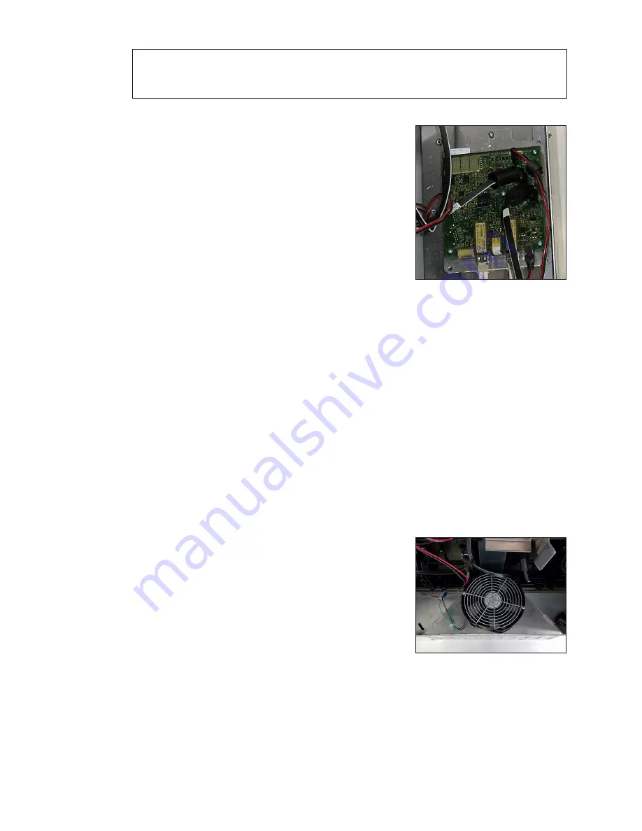
Replace a Display Fan
Required Tools:
Phillips screwdriver, side cutter, cable ties
If needed, remove the fan plenum following the steps in
1�
Locate and disconnect the 3-pin Mate-N-Lok connector.
2�
Use the Phillips screwdriver to loosen the two fan
.
3�
Cut the cable tie holding the harness to the plenum.
4�
Remove the fan from the display.
5�
Reverse
Steps 1–4
to install the new fan.
6�
Attach harness to the fan plenum using a cable tie.
.
Figure 28:
ProLink Router
Connected For Self-Test
Figure 29:
Display Fan
Содержание DXB Series
Страница 30: ...This page intentionally left blank...
Страница 32: ...This page intentionally left blank...


