


Access and Troubleshoot the Webcam
23
9 Access and Troubleshoot the Webcam
The information is this section describes how to retract
the webcam to the display face for service and provides
some basic troubleshooting steps. Work with the help
desk to verify the camera is aligned and in focus after
servicing or cleaning the webcam.
Retract the Webcam to the Display
Face (Rotation Mount Only)
1�
Remove the three short bolts from the elbow
.
Do not remove the long bolts in the collar.
2�
Use the handle to carefully pivot the webcam arm to
the front of the catwalk.
Note:
Verify that webcam cables are not pulled or
pinched when pivoting the webcam arm.
3�
Return the webcam arm to the original position
when servicing the webcam.
4�
Replace and tighten the three short bolts.
5�
Work with Daktronics help desk to verify the webcam
is focused and functioning properly.
Troubleshoot the Webcam
This section provides some basic power troubleshooting
steps to perform if the webcam is not functioning
below.
Issue
Troubleshooting Steps
Both LED
indicators on
the webcam
are off.
• Check Cat5 connections inside surge protector to ensure they are secure.
• Verify M12 connection for camera on back of display is securely fastened.
• Inside the ISP box, verify camera is connected to port 1 on POE side of POE
switch and LED indicators are on.
• Verify power connection to POE switch and AC adapter are securely
fastened.
• If all connections are securely fastened but indicators are off, work with the
help desk to further troubleshoot the issue.
• The POE surge may be damaged. Use a RJ45 coupler to bypass.
Short
Bolt (x3)
Handle
Figure 38:
Webcam Arm Bolts
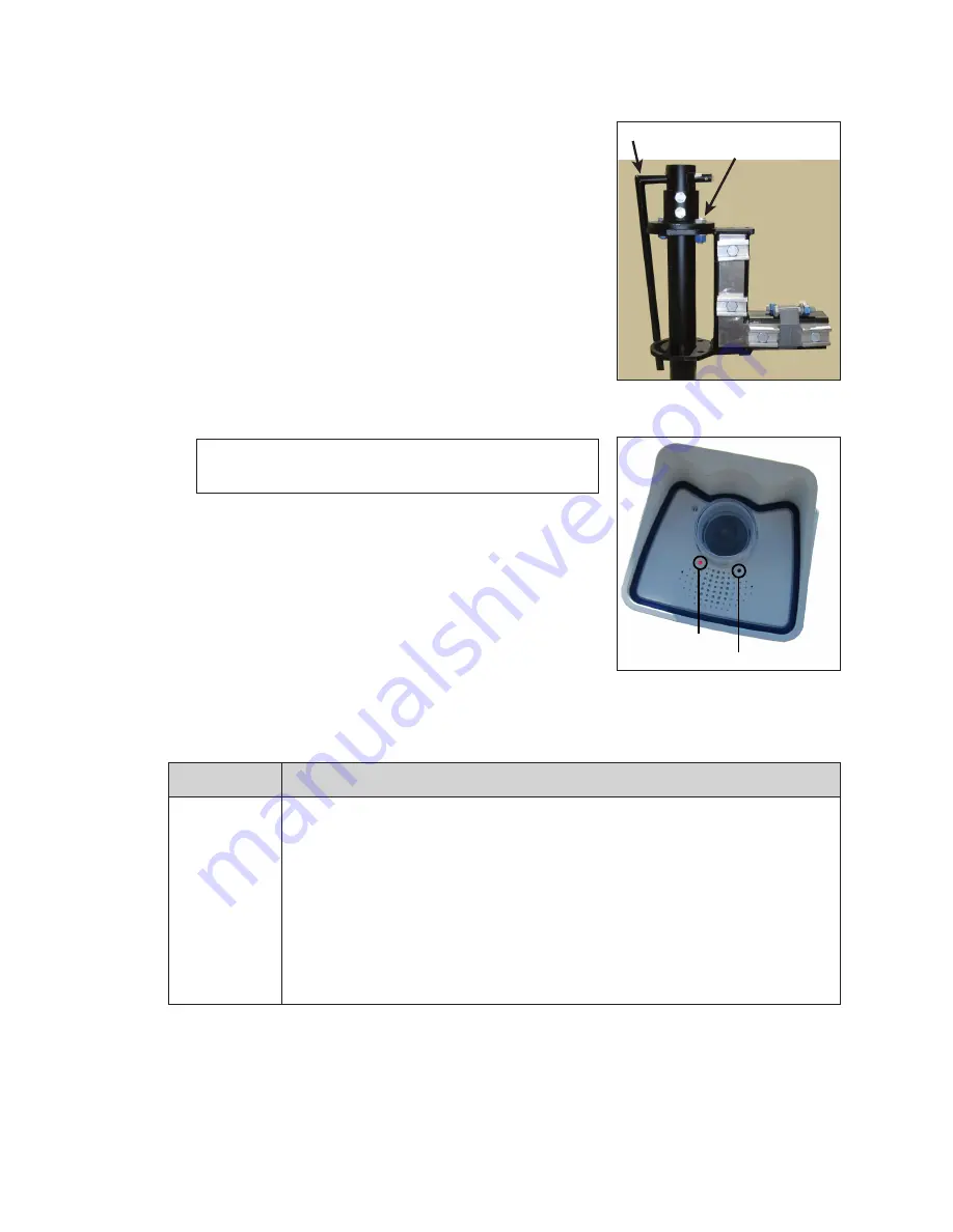
Red LED
Green LED
Figure 39:
Webcam LED Status
Indicators
Содержание DB-66 Series
Страница 4: ...ii This page intentionally left blank...
Страница 30: ...26 This page intentionally left blank...
Страница 32: ...28 This page intentionally left blank...


