Test and Remove Modules
13
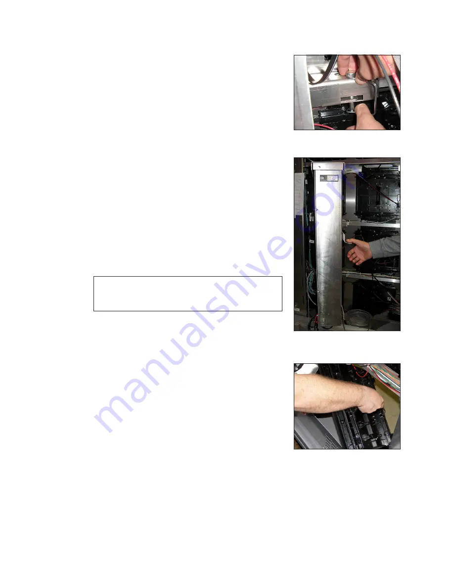
Remove a Module from Behind Internal Enclosures
Required Tools:
1
/
8
″ hex head wrench, module lanyard
1�
Remove pins from one side of the enclosure (ISP,
term panel, SmartLink, and spare parts rack). Refer to
.
2�
While holding the enclosure, allow it to slowly rotate
open and out of the way. Refer to
.
3�
Follow the steps in
to reinstall a module.
4�
If needed, remove all pins that hold the enclosure
in place in the cabinet. Lift the enclosure out of the
cabinet and set aside while ensuring power and
signal cables do not get pinched.
5�
Reverse Steps 1 - 4 to replace the enclosure.
Reinstall a Module (Rear Access)
When installing new modules, place them in the outer ring
of the display.
1�
Rotate and carefully guide the module through the
module opening, as shown in
Note:
To ensure proper alignment, verify the word
TOP printed on the back of the module is to
the top left of the face sheet.
2�
Once the module is through the display face, align
the module with the face sheet. Ensure the lanyard
or cables do not pinch between the module and the
display.
3�
After the module is in place, use the module lanyard
rings or the lanyard to pull the module firmly against
the face sheet.
4�
With a
1
/
8
″ hex head wrench, turn the latch gear
approximately a quarter-turn counter-clockwise to
engage the latch.
5�
Connect the SATA and power cables to the back of
the module.
Figure 15:
Remove Pins
Figure 16:
Hinge ISP Enclosure
Out of Display
Figure 17:
Rotate Module To
Clear Face Sheet
Содержание 65 P2210
Страница 4: ...This page intentionally left blank...
Страница 30: ...This page intentionally left blank...


