page 2
MAN#650265
INSTALLATION:
1. Disconnect the battery to prevent possible damage to the electrical system or gauge during install.
2. Remove the rubber mounting ring and stock gauge by pushing the gauge out from behind the dash. The UTV gauge
will mount in this mounting location.
3. If not installing temp and oil sensor pack (Dakota Digital part number SEN-24-1),
skip to step 10
.
STEPS 4 THROUGH 9: INSTALLATION OF SENSOR PACK (SEN-24-1)
4. Remove the seats, console/engine cover, and center floor/front drive shaft cover (refer to service manual). This
allows access to sensor locations on the engine and wire routing locations.
5. Temperature sender installation
(NOTE: If engine is warm, allow it to cool before continuing!)
:
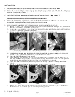
a. Remove the bleed screw from the thermostat housing (located on engine behind passenger seat) and set aside.
Be prepared to catch any coolant that may drain out.
b. Loosen hose clamp and remove coolant hose from thermostat housing. Again, be prepared to catch coolant as
this will drain some of the coolant from the system.
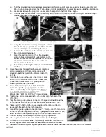
c. Remove two bolts holding thermostat housing and remove housing from front of engine.
d. Install the provided thermostat housing with the original housing bolts. Be careful to position the thermostat
correctly into the engine block. Tighten to torque specified in service manual.
e. Place hose and hose clamp onto new housing.
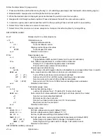
f.
Turn supplied temperature sensor into new housing and tighten with a wrench. DO NOT use Teflon tape or
other sealer as this could cause errors in the temperature reading. The sensor should be able to be tightened
enough to prevent leaks without having to turn the sensor completely into the housing.
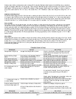
g. Insert coolant bleed screw from original housing into the new housing. Tighten to torque specified service
manual.
h. Connect the spade terminal from supplied harness to the peg on end of temp sensor.
i.
Refill cooling system. Be sure to check for leaks and proper coolant level after running engine first few times.
Check the service manual for the proper coolant filling/bleeding procedure.
6. Oil sender installation:
(Step 5h)
(Step 5g)
(Step 5f)
(Step 5c)
(Step 5b)
(Step 5a)


