MAN#650780
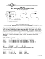
Mounting the cylinder head temperature sensor:
The sensor ring terminal can be installed under a cylinder head bolt on the engine or installed under a spark
plug. Using, or not using, the crush washer on the spark plug is up to the individual. It should not make that much
difference if it is used. The gapping of the plug is more important. Not using a washer when it is required, could place
the plug closer to the piston head than tolerance requires.
To set or change the ID numbers:
The ID will not normally need to be changed. The following procedure will allow the BIM-12-2 to automatically
select a new, u
nused set of ID’s.
Make sure that all of the senders are connected first.
•
Hold the switch beside the BIM terminal strip while turning the key on. The BIM display will show the current
revision code while this is held.
•
Release the switch. The display will show the current number of senders connected.
“
−−
”.
•
If the correct number of sensors is shown, Press the switch. The BIM display begin sequencing a bar across
the display
“
−
” “
−
” “
−
”.
•
Release the switch. The BIM will restart with the new settings.
The labels and warning points are set up through the gauge display system.
Only VFD3/3X controls with a plastic case support adding BIM’s.
For VFD3, VFD3X, and VHX systems follow these steps:
•
Make sure the BIM units are all connected to the gauge control box with the power/data harness.
•
Hold the SW1 switch from the gauge system control box while turning the key on. The message display
should show SETUP.
•
Release SW1.
•
Press and release SW1 until BIM is shown on the message display.
•
Press and hold SW1. The message display should show SCAN followed by the number of BIM channels
detected. Release SW1.
•
If 0 is shown, check all connections and then press and hold SW1 with SCAN shown to retry reading the
modules.
•
Otherwise, if any other number is shown, press and release SW1 until SETUP is shown.
•
Press and hold SW1 until the speed display shows “ – ” or the message changes.
•
Release SW1. On the VFD3 systems the message display will show the label assigned to the first channel
found and the speed display will sh
ow “C” followed by the channel ID number. On the VHX systems the
message display will show “CH” followed by the channel ID number on one line and the label currently
assigned on the second line.
•
Press and release SW1 until the desired channel ID number is shown.
•
Press and hold SW1. The message display will show “LABEL”.
•
Release SW1. The message display will show the label assigned to this channel.
•
Press and release SW1 until the desired label is shown.
•
Press and hold SW1. The message display will show
“WARN”.
•
Release SW1. The message display will show “H” followed by the current high warning point or will flash the
warning point.
•
Press and release SW1 to change the high warning point to the desired value.
•
Press and hold SW1. The message display will no
w show “DONE”.
•
This can be repeated for additional channels, or the key can be turned off to exit setup.


