


6/02
16
BLADE GUIDE ADJUSTMENT
NOTE: The following instructions are for one
guide arm; procedure is same for both. Left hand
guide arm is shown in Figure 6.
1. Loosen nut (A, Fig. 6) and turn eccentric axle (B)
until there is no light gap between rollers and
blade…do not pinch the blade. Tighten nut (A).
2. Vertical and radial adjustment is provided by the
clearance in the guide mounting holes (C, Fig. 6).
This allows squaring of the blade to the bed, and
holding the blade in the natural blade line.
3. Proper guide adjustment may require adding or
removing washer (shims) (D, Fig. 6) for correct
bearing height (E, fig. 6)
FRAME BALANCE SPRING ADJUSTMENT
To check for proper balance spring adjustment, lift frame at eh handle with an extension type
scale (fish scale). Frame should weigh 12-15 pounds; if no, adjust by turning nut on the tension
screw at bottom of spring.
FEED CYLINDER BLEEDING
Air trapped in the hydraulic cylinder can cause the down feed of the machine head to be
erratic or “bouncy”. Before taking corrective steps observe CAUTION.
CAUTION: UNDER NO CIRCUMSTANCES SHOULD THE HYDRAULIC TUBING CONNECTIONS
BE LOOSENED OR DISCONNECTED WITH THE MACHINE HEAD IN THE UP POSITION.
Bleed the hydraulic cylinder circuit as follows:
1. Place a long neck funnel in the oil cup (diameter of funnel neck must be almost the same
size of the fill cup.
2. Pour oil into the funnel. *Make sure there is a sufficient amount of oil in the funnel so that
air does not get drawn into cylinder.
3. With head feed valve open, raise and lower head about four times.
4. Pour more oil into the funnel.
5. Close head feed valve.
6. Raise head.
7. Open feed valve and lower head.
8. Repeat 5,6 & 7 several times.
9. Remove funnel.
D
E
Содержание J-10
Страница 8: ...6 02 8 ELECTRICAL CONTROL DIAGRAMS ...
Страница 9: ...6 02 9 SINGLE PHASE ELECTRICAL DIAGRAM ...
Страница 10: ...6 02 10 THREE PHASE ELECTRICAL DIAGRAM ...
Страница 18: ...6 02 18 SAWING PROBLEMS SOLUTIONS ...
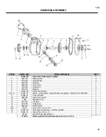
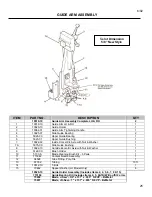
Страница 19: ...6 02 19 ASSEMBLIES AND PARTS LIST Section 3 ...
Страница 23: ...6 02 23 HYDRAULIC ASSEMBLY ...


