Daikin WSC063 Скачать руководство пользователя страница 37

IM 1044-2 

Centrifugal Chillers 

37


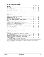
Prestart System Checklist 

Yes 

No 

N/A 

Chilled Water 

Piping complete .................................................................................................................  


Water system filled, vented ...............................................................................................  


Pumps installed, (rotation checked), strainers cleaned ......................................................  


Strainer installed at evaporator inlet             


Controls (3-way, face and bypass dampers, bypass valves, etc.) operable ........................  


Water system operated and flow balanced to meet unit design requirements ...................  


Condenser Water (*) 

Cooling tower flushed, filled and vented  .........................................................................  


Pumps installed, (rotation checked), strainers cleaned  .....................................................  


Strainer installed at condenser inlet              


Controls (3-way, bypass valves, etc.) operable  ................................................................  


Water system operated and flow balanced to meet unit requirements  ..............................  


Electrical 

115-volt service completed, but not connected to control panel  ......................................  


Power leads connected to starter; load leads run to compressor ready for 
   connection when service engineer is on hand for start-up  .............................................  


(Do not connect starter or compressor terminals)  

All interlock wiring complete between control panel and complies with specifications ..  


Starter complies with specifications  .................................................................................  


Pump starters and interlock wired  ....................................................................................  


Cooling tower fans and controls wired  .............................................................................  


Wiring complies with National Electrical Code and local codes  .....................................  


Condenser pump starting relay (CWR) installed and wired  .............................................  


Miscellaneous 

Oil cooler water piping complete (units with water cooled oil coolers only)  ...................  


Relief valve piping complete  ............................................................................................  


Thermometer wells, thermometers, gauges, control wells, controls, etc., installed  .........  


Minimum system load of 80% of machine capacity available for testing 
and adjusting controls  ......................................................................................................  


(*) Includes heating hot water on heat recovery units. 

Note

:  This checklist must be completed and sent to the local 

Daikin

 service location two 

weeks prior to start-up. 

Содержание WSC063

Страница 1: ...Maintenance Manual IM 1044 2 Centrifugal Compressor Water Chillers Group Chillers Part Number 331374801 REV 0A Date August 2012 2013 Daikin Applied Models WSC WDC WCC HSC Includes High Voltage 10 11k...

Страница 2: ...57 Operator Schools 57 Warranty Statement 57 Hazard Identification DANGER Dangers indicate a hazardous situation which will result in death or serious injury if not avoided WARNING Warnings indicate p...

Страница 3: ...100 113 and 126 size WDC and WCC units are available in high voltage 10 11kV These models will have different dimensions weights and installation details than the standard low medium voltage models S...

Страница 4: ...on This will aid in handling the equipment Extreme care must be used when rigging the equipment to prevent damage to the control panels or refrigerant piping See the certified dimension drawings inclu...

Страница 5: ...porator and condenser tubes are rolled into the tube sheets to permit replacement if necessary The length of the vessel should be allowed at one end Doors or removable wall sections can be utilized fo...

Страница 6: ...the mounting slab or framework but should this be desirable 1 1 8 28 5 mm mounting holes are provided in the unit support at the four corners Note Units are shipped with refrigerant and oil valves cl...

Страница 7: ...ndenser Water Temperature EXV Min ECWT 5 25 0 88 LWT DTFL PLD 100 22 PLD 100 2 ECWT Entering condenser water temperature LWT Leaving chilled water temperature DTFL Chilled Water Delta T at full load P...

Страница 8: ...llers are selected for lower kW per ton the cooling tower fan motor power becomes a higher percentage of the total peak load chiller power Daikin s Energy Analyzer program can optimize the chiller tow...

Страница 9: ...a 2 pass configuration and copper tubing may have an over under connection configuration on the evaporator rather than the side by side configuration shown here Consult Certified Drawings for exact c...

Страница 10: ...mal dispersion flow switches are available from Daikin as a factory mounted option It is mounted in an evaporator and condenser water nozzle and factory wired A paddle type flow switch can be supplied...

Страница 11: ...d to be sure that it conforms to the system design Some form of temperature control is also required if an uncontrolled tower can supply water below about 65 F 18 C If tower fan control is not adequat...

Страница 12: ...ers IM 1044 2 Figure 7 Heat Recovery Schematic EVAPORATOR TOWER CONDENSER RECOVERY CONDENSER AUXILIARY HEATER HEAT LOAD TC TC COOLING LOAD OPEN CIRCUIT TOWER HEAT RECOVERY CHILLER LEGEND TC TEMPERATUR...

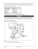
Страница 13: ...IM 1044 2 Centrifugal Chillers 13 Field Insulation Guide Figure 8 Insulation Requirements Cooling only Units...

Страница 14: ...14 Centrifugal Chillers IM 1044 2...

Страница 15: ...7 6 2543 1152 478 217 148 67 1 E2012 X 37 139 84 7 8 2862 1296 478 217 148 67 1 E2209 X 38 145 66 6 1 2708 1227 600 272 175 79 1 E2212 X 45 170 90 8 3 3071 1391 600 272 175 79 1 E2216 X 79 301 144 13...

Страница 16: ...alves C1809 X 597 271 43 162 1887 856 2 C1812 X 845 384 44 166 2050 930 2 C2009 X 728 330 47 147 1896 860 2 C2012 X 971 440 62 236 2528 1147 2 C2209 X 822 372 73 278 2596 1169 2 C2212 X 1183 537 76 29...

Страница 17: ...8863 22007 9982 WSC087 2609 2209 651 295 10980 4981 11990 5439 12180 5525 13190 5983 WSC087 2612 2212 859 389 12309 5583 13549 6146 13509 6128 14749 6690 WSC087 2609 2609 686 311 11716 5314 12960 587...

Страница 18: ...DC087 4216 4216 44470 20189 51463 23364 47204 21431 54197 24605 WDC100 113 3616 3616 41816 18967 46513 21098 See Note 2 See Note 2 WDC100 113 126 7kV 4216 4216 50470 22893 57463 26065 See Note 2 See N...

Страница 19: ...water it is important that the water pressure drop across the evaporator is greater than the pressure drop across the oil cooler or insufficient oil cooler flow will result If the pressure drop across...

Страница 20: ...water in the 45 F to 65 F 7 C to 18 C range considerably less water will be used and the pressure drop will be greatly reduced When supplied with city water the oil piping must discharge through a tra...

Страница 21: ...COOLING TOWER OPEN DRAIN DRAIN VALVE OR PLUG SOLENOID VALVE OIL COOLER WATER SUPPLY STOP VALVE STRAINER MAX 40 MESH COOLING TOWER MAKEUP DISCHARGE ABOVE HIGHEST POSSIBLE WATER LEVEL R S Oil Reservoir...

Страница 22: ...be followed Condensers have two relief valves as a set with a three way valve separating the two valves large condensers will have two such sets One valve remains active at all times and the second v...

Страница 23: ...A pipe increaser must always be installed at the valve outlet Common Piping According to ASHRAE Standard 15 the pipe size cannot be less than the relief valve outlet size The discharge from more than...

Страница 24: ...ian the contractor should obtain and apply the following items on medium voltage above 600 volts applications Materials required 1 Loctite brand safety solvent 12 oz package available as Daikin part n...

Страница 25: ...ve to hold it in place until the terminal box is mounted The gasket must be located such that the gasket holes align with the threaded holes in the casting 2 Remove the terminal box door before liftin...

Страница 26: ...ench and tighten as shown below The buss bars are factory connected to the box main power terminals and field connected to the motor terminals Use Scotch Linerless Rubber Splicing Tape to cover the co...

Страница 27: ...al box power connectors are made to the landing points shown in Figure 15captive and attached with a bolt already in the connector Figure 15 Terminal Box Mounted Front View Figure 16 Terminal Box Moun...

Страница 28: ...ear Temperature Sensors connect to the controller s J6 terminal strip Brown B6 White B7 Blue B8 Black Ground Motor Terminal Box to Chiller Control Panel Field wiring is required between the terminal b...

Страница 29: ...1 If the unit is supplied with a factory mounted starter or VFD the control circuit power supply is factory wired from a transformer located in the starter or VFD 2 A freestanding starter or VFD furni...

Страница 30: ...Diagram on page 32 or on the cover of the control panel for proper connections The purpose of the water flow interlocks is to prevent compressor operation until such time as both the evaporator water...

Страница 31: ...wire between 83 81 The alarm is operator programmable The maximum rating of the alarm relay coil is 25 VA 5 Remote on off control of unit can be accomplished by installing a set of dry contacts betwe...

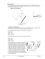
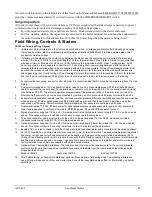
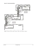
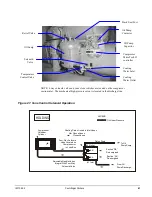
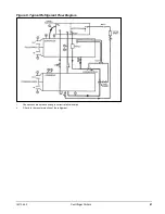
Страница 32: ...32 Centrifugal Chillers IM 1044 2 Figure 19 Field Control Wiring Diagram...

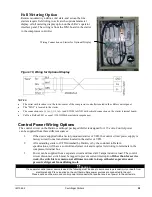
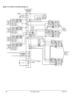
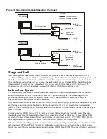
Страница 33: ...IM 1044 2 Centrifugal Chillers 33 Figure 20 Field Wiring Remote Starter...

Страница 34: ...ikin startup technician is responsible is to check the wiring and make the appropriate control changes pLAN Wiring Connect chillers together pLAN RS485 wiring as shown in Figure 21 on the following pa...

Страница 35: ...ller Chiller D would be connected to chiller C same as chiller C to chiller B Chiller A PIGTAIL 485 OPDR C A B UCM J10 J11 BLU WHT WHT BLU SHIELD UNIT CONTROL J11 PORT Chiller B 485 OPDR C BLU WHT WHT...

Страница 36: ...ence The Modes setpoints will do several different types of operation Normal Efficiency Standby etc as described in the operating manual The same Modes setting must be replicated on each chiller in th...

Страница 37: ...starter load leads run to compressor ready for connection when service engineer is on hand for start up Do not connect starter or compressor terminals All interlock wiring complete between control pa...

Страница 38: ...contact your Daikin representative Standby Power It is essential that any centrifugal chiller connected to standby power come to a complete stop before being restarted on grid power This is usually n...

Страница 39: ...5 volt Circuit Breaker Latch Relay Heater Relay Compressor Relay Oil Pump Overload Relay Reset Button Oil Pump Contactor Oil Pump Starting Capacitor Terminal Board CTB2 Compressor Microprocessor Trans...

Страница 40: ...d Figure 28 for solenoid action Note that both solenoids cannot be energized simultaneously Vane Speed Metering Valves The speed at which the capacity control vanes are opened or closed can be adjuste...

Страница 41: ...Sump Section SB De energized Section SA De energized From Oil Pump Discharge Adjustable Needle Valves Integral With Four Way Solenoid Valve HOLDING NOTE 4 way solenoid valve and vane close switches ar...

Страница 42: ...n in Table 15 can be used for proper operation of the hydraulic system and bearing lubrication system Each unit is factory charged with the correct amount of the recommended lubricant Under normal ope...

Страница 43: ...Gal Can 735030432 Rev 47 735030433 Rev 47 735030435 Rev 47 Compressor Oil Label 070200106 Rev OB NOTES 1 Approved oil from two suppliers can be mixed although they have slightly different viscosity 2...

Страница 44: ...r from short cycling under light load conditions It also reduces surge potential on heat recovery units The factory setpoint for bringing on hot gas bypass is 40 of RLA Condenser Water Temperature Whe...

Страница 45: ...equipment Only authorized and trained service personnel should attempt this service For qualified assistance contact your local Daikin service location After the system is once placed into operation...

Страница 46: ...ome foaming can occur but the check valve should limit leakage from other compressor cavities Remove the filter replace with new element and replace filter cover using a new gasket Reopen the valve in...

Страница 47: ...IM 1044 2 Centrifugal Chillers 47 Figure 8 Typical Refrigerant Flow Diagram 1 Connections are not necessarily in correct relative location 2 Filter is for burnout protection of the refrigerant...

Страница 48: ...dicates a possible insulation defect or moisture and must be further checked CAUTION Never Megger a motor while in a vacuum Severe motor damage can result 6 The centrifugal compressor must rotate in t...

Страница 49: ...n result in corrosion erosion sliming scaling or algae formation It is recommended that the service of a reliable water treatment company be used Daikin assumes no responsibility for the results of un...

Страница 50: ...reached disconnect the gas cylinder Pressure Testing No pressure testing is necessary unless some damage was incurred during shipment Damage can be determined upon a visual inspection of the exterior...

Страница 51: ...uld be interrupted and prestart checks made before attempting to complete refrigerant charge The compressor must not be started at this time Preliminary check must first be completed NOTE It is of utm...

Страница 52: ...in some mineral oils Lead The source of lead in Daikin centrifugal chillers is the thread sealant compounds used during chiller assembly The presence of lead in the lubricating oil in Daikin chillers...

Страница 53: ...rom previous sample results or after a failure The presence of residual materials from a failure should be taken into consideration in subsequent analysis While the unit is in operation the sample sho...

Страница 54: ...ystem Clean Oil Cooler Strainer water X Oil Cooler Solenoid Operation O Oil Appearance clear color quantity O Oil Filter Pressure Drop O Oil Analysis Note 5 X Oil change if indicated by oil analysis X...

Страница 55: ...ndling electrical components only fully qualified technicians must attempt service 2 Approach temperature the difference between the leaving water temperature and the saturated refrigerant temperature...

Страница 56: ...talled keep it pumped down as shipped from the factory and close all refrigerant valves 5 Keep oil sump valves closed to avoid refrigerant migration to the oil sump Over a long term the refrigerant wi...

Страница 57: ...concerning the many services available contact your local Daikin service office Operator Schools Training courses for Centrifugal Maintenance and Operation are held through the year at the Daikin Tra...

Страница 58: ...ick on training or call 540 248 9646 to speak to the Training Department Warranty All Daikin equipment is sold pursuant to Daikin standard terms and conditions of sale including Limited Product Warran...

Отзывы: