Daikin VRV III RXYQ-PY1K Скачать руководство пользователя страница 16

Installation manual

13

RXYQ8~1 RXYQ8~12P7YLK

VRVIII System air conditioner

4PW41760-1

8.5.

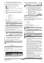
System examples

(See figure 15)

8.6.

Leading power line and transmission line

Be sure to let the power line and the transmission line pass
through a conduit hole.

Lead the power line from the upper hole on the left side plate,
from the front position of the main unit (through the conduit hole
of the wiring mounting plate) or from a knock out hole to be
made in the unit's bottom plate. 

(See figure 18)

Precautions when knocking out knockout holes

To punch a knockout hole, hit on it with a hammer.

After knocking out the holes, we recommend you paint the
edges and areas around the edges using the repair paint to
prevent rusting.

When passing electrical wiring through the knockout holes,
remove any burrs from the knockout hole edges. Wrap the wiring
with protective tape in order to prevent damage to the wires, put
the wires through field supplied protective wire conduits at that
location, or install suitable field supplied wire nipples or rubber
bushings into the knockout holes.

8.7.

Field line connection: transmission wiring and 
cool/heat selection

In case of RXYQ8~12 

(See figure 19)

In case of RXYQ16~36 

(See figure 20)

The interconnecting wiring between the outdoor units in the
same piping system must be connected to the Q1/Q2 (Out Multi)
terminals. Connecting the wires to the F1/F2 (Out-Out) terminals
results in system malfunction.

The wiring for the other systems must be connected to the F1/F2
(Out-Out) terminals of the P-board in the outdoor unit to which
the interconnecting wiring for the indoor units is connected.

The base unit is the outdoor unit to which the interconnecting
wiring for the indoor units is connected.

1

Field power supply

2

Main switch

3

Earth leakage breaker

4

Outdoor unit

5

Indoor unit

6

Remote controller

Power supply wiring (sheathed cable)
- outdoor 3 phase 380 ~ 415 V
- indoor 1 phase 230 V

Transmission wiring (sheathed cable) (16 V)

1

Electric wiring diagram. Printed on the back of the electric box lid.

2

Power wiring and ground wiring between outdoor units (inside 
conduit)
(When the wiring is routed out through the lateral panel.)

3

Transmission wiring

4

Pipe opening

5

Conduit

6

Power wiring and ground wiring

7

Cut off the shaded zones before use.

8

Through cover

1

Knockout hole

2

Burr

3

If there are any possibilities that small animals enter the system 
through the knockout holes, plug the holes with packing materials 
(to be prepared on-site).

2

3

1

Use a power wire pipe for the power wiring.

Outside the unit, make sure the weak low voltage
electric wiring (i.e. for the remote control, between
units, etc.) and the high voltage electric wiring do not
pass near each other, keeping them at least 50 mm
apart. Proximity may cause electrical interference,
malfunctions, and breakage.

Be sure to connect the power wiring to the power
wiring terminal block and secure it as described under

"8.8. Field line connection: power wiring" on page 15

.

Inter-unit wiring should be secured as described in

"8.7. Field line connection: transmission wiring and
cool/heat selection" on page 13

.

Secure the wiring with the accessory clamps so
that it does not touch the piping and no external
force can be applied to the terminal.

Make sure the wiring and the electric box lid do not
stick up above the structure, and close the cover
firmly.

1

Cool/heat selector (not required for cooling only units)

2

Outdoor unit PC board (A1P)

3

Take care of the polarity (not required for cooling only units)

4

Use the conductor of sheathed wire (2 wire) (no polarity)

5

Terminal board (field supply)

6

Indoor unit

7

Outdoor unit

1

Unit A (Master unit)

2

Unit B (Slave unit)

3

Unit C (Slave unit)

4

To slave unit(s)

5

To indoor unit

6

To outdoor unit

7

To cool/heat selector

Содержание VRV III RXYQ-PY1K

Страница 1: ...INSTALLATION MANUAL RXYQ8P7Y1K RXYQ10P7Y1K RXYQ12P7Y1K RXYQ8P7YLK RXYQ10P7YLK RXYQ12P7YLK System air conditioner...

Страница 2: ...XYQ16 32 2 1 h1 h2 a 10 mm b 300 mm c 10 mm d 500 mm a 50 mm b 100 mm c 50 mm d 500 mm a 200 mm b 300 mm a 10 mm b 300 mm c 10 mm d 500 mm e 20 mm a 50 mm b 100 mm c 50 mm d 500 mm e 100 mm a 200 mm b...

Страница 3: ...OUT D UNIT TO MULTI UNIT A1P 3 A B C F1 F2 F1 F2 Q1 Q2 Q1 Q2 A1P 4 4 5 6 2 1 3 Q1 Q2 7 5 3 4 1 6 6 2 2 TO IN D UNIT F1 F2 DS1 1 2 3 4 OFF ON O U T I N F1 F2 P1 P2 P1 P2 1 A B C A B C 1 DS1 1 2 3 4 OF...

Страница 4: ...for their installation 1 1 Combination The indoor units can be installed in the following range Always use appropriate indoor units compatible with R410A To learn which models of indoor units are com...

Страница 5: ...5 35 RXYQ24 RXYQ12 RXYQ12 300 780 39 RXYQ26 RXYQ8 RXYQ8 RXYQ10 325 845 42 RXYQ28 RXYQ8 RXYQ10 RXYQ10 350 910 45 RXYQ30 RXYQ8 RXYQ10 RXYQ12 375 975 48 RXYQ32 RXYQ10 RXYQ10 RXYQ12 400 1040 52 RXYQ34 RXY...

Страница 6: ...easures in order to prevent that the outdoor unit be used as a shelter by small animals Small animals making contact with electrical parts can cause malfunctions smoke or fire Please instruct the cust...

Страница 7: ...G 1 Packaging material 2 Opening large 3 Belt sling 4 Opening small 40x45 5 Protector NOTE Use a belt sling of 20 mm wide that adequately bears the weight of the unit NOTE Use filler cloth on the fork...

Страница 8: ...size is not available stick to the original pipe diameter which may result in a small capacity decrease 6 3 Pipe connection Be sure to perform a nitrogen blow when brazing and to read the paragraph C...

Страница 9: ...on into the piping side Pattern 1 Pattern 2 Prohibited patterns change to pattern 1 or 2 1 Pinched piping 2 Stop valve 3 Service port 4 Point of melting the brazing metal Precautions when connecting f...

Страница 10: ...e than 500 mm of straight section can be ensured Improper installation may lead to malfunction of the outdoor unit 6 Piping length restrictions Make sure to perform the piping installation within the...

Страница 11: ...be used with R410A How to select the refnet joint When using refnet joints at the first branch counted from the outdoor unit side Choose from the following table in accordance with the capacity of the...

Страница 12: ...es must be doubled except main pipe and the pipes that not increase the pipe size a b 2 c 2 d 2 e 2 f 2 g 2 h i j k l m n p 1000 m Indoor unit to the nearest branch kit 40 m h i j p 40 m The differenc...

Страница 13: ...side stop valve Gas side stop valve Performing the airtightness test and vacuum drying Valve A must always be shut Otherwise the refrigerant in the unit will pour out Close Open Open Close Close NOTE...

Страница 14: ...stor current limiting S1NPH Pressure sensor high S1NPL Pressure sensor low S1PH S2PH Pressure switch high T1A Current sensor A6P A7P SD1 Safety devices input V1R Power module A3P A4P A8P V2R Diode bri...

Страница 15: ...prevent malfunctioning of the earth leakage breaker itself Earth leakage breakers that are especially designed for protecting ground faults must be used in conjunction with main switch and fuse for us...

Страница 16: ...akage breaker 4 Outdoor unit 5 Indoor unit 6 Remote controller Power supply wiring sheathed cable outdoor 3 phase 380 415 V indoor 1 phase 230 V Transmission wiring sheathed cable 16 V 1 Electric wiri...

Страница 17: ...16 branches are possible for unit to unit cabling No branching is allowed after branching See figure 16 Never connect the power supply to transmission wiring terminal block Otherwise the entire system...

Страница 18: ...ying power wiring Do not connect wiring of different thicknesses to the power terminal block Slack in the power wiring may cause abnormal heat When connecting wiring which is the same thickness do as...

Страница 19: ...ansmission wiring between outdoor and indoor unit outdoor and COOL HEAT selector etc 11 CHARGING REFRIGERANT The outdoor unit is factory charged but depending on the length of the piping when installe...

Страница 20: ...d line stop valve 9 5 a a The model RXYQ12 supports field piping of 12 7 on the accessory pipe supplied with the unit Gas line stop valve 19 1 25 4 b b The model RXYQ10 supports field piping of 22 2 o...

Страница 21: ...r the power is on via the service lid which is in the lid of the electric box Operate switches with an insulated stick such as a ball point pen to avoid touching the life parts Make sure to re attach...

Страница 22: ...tton once if the LEDs combination is not as in the figure below 3 Press the button once 4 Hold the button down for 5 seconds or more 5 Charging mode judgement For automatic charging the charging must...

Страница 23: ...d check the LEDs and check if the P9 code is displayed on the remote controller When the charging amount is little the PE code may not be displayed but instead the P9 code will be displayed immediatel...

Страница 24: ...mode is not possible in some cases The unit will automatically select the cooling mode or heating mode for charging Continue with the manually charging in cooling mode OR in heating mode Charging in...

Страница 25: ...e controller malfunction code display on page 22 H1P H2P H3P H4P H5P H6P H7P w c c w w w w BS4 TEST BS4 TEST BS1 MODE LED display Default status before delivery Micro computer operation monitor Mode R...

Страница 26: ...form the overcharge judgement procedure again When there is no more overcharging of refrigerant detected restart the automatic refrigerant charging from 1 Start of automatic charging refrigerant as ex...

Страница 27: ...uch as a ball point pen to avoid touching live parts Make sure to re attach the inspection cover 1 into the switch box cover 2 after the job is finished WARNING ELECTRIC SHOCK Caution when performing...

Страница 28: ...selection on page 13 not installed factory setting 2 4 NOT USED DO NOT CHANGE THE FACTORY SETTING What to set with dip switch DS2 1 4 NOT USED DO NOT CHANGE THE FACTORY SETTING What to set with dip s...

Страница 29: ...he external control adapter F power consumption limitation setting via the external control adapter G enabling function of the low noise operation level setting and or power consumption limitation set...

Страница 30: ...pleted Normal operation will be possible after 5 minutes If a malfunction code is displayed on the remote controller correct the malfunction and perform the check operation again as decribed in Correc...

Страница 31: ...tion will be prohibited 2 Cut off the power supply to the indoor units and the outdoor unit with the circuit breaker After the power supply to one side is cut off cut off the power supply to the other...

Страница 32: ...such as the following calculate the volume of A B as a single room or as the smallest room 3 Calculating the refrigerant density using the results of the calculations in steps 1 and 2 above If the re...

Страница 33: ...5 1 7 10 3 2 9 6 6 6 6 7 4 11 8 6 6 6 6 6 6 7 7 9 8 4 11 6 6 1 10 3 2 6 6 6 6 28 13 6 9 8 1 2 4 3 5 14 15 16 12 11 10 10 7 29 13 14 3 5 4 2 1 7 8 9 6 10 10 11 10 2 2 12 9 9 30 13 14 3 5 4 2 1 7 8 9 6...

Страница 34: ...4PW41760 1 Copyright Daikin...

Отзывы: