


English
14
11-2-1 Procedure of Adding Refrigerant charging
1.
Make sure the following works are complete in accordance with
the installation manual.
Piping work
Wiring work
Air tight test
Vacuum drying
Installation work for BS, indoor unit
2.
Calculate the “additional charging amount” using “How to calcu-
late the additional refrigerant to be charged” in “
6-5 Example of
connection
”.
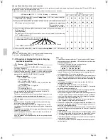
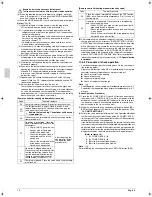
3.
Open the valve B (
See the figure 30
. The valve A,C and the liquid
pipe, suction gas pipe, HP/LP gas pipe shutoff valves must be left
closed), and charge the refrigerant of the “additional charging
amount” from the liquid side shutout valve service port.
(Refer to figure 30)
1.
Measuring device
2.
R410A tank (with siphon)
3.
Charge hose
4.
Refrigerant charge port
5.
HP/LP gas pipe shutoff valve
6.
Suction gas shutoff valve
7.
Liquid pipe shutoff valve
8.
Valve A
9.
Valve B
10.
Valve C
11.
Outdoor unit
12.
To BS, indoor unit
13.
Field pipings
14.
Refrigerant flow
15.
Shutoff valve
16.
Service port
4.
If the “additional charging amount” was charged fully, close the
valve B and go to step 6.
If the “additional charging amount” was not charged fully, close
the valve B and go to step 5.
5.
Perform the refrigerant charging following [Automatic refrigerant
charging operation procedure] as shown below. And charge the
remaining refrigerant of the “additional charging amount”.
Note
•
For performing the automatic refrigerant charging operation, the
push button on the PC-bord (A1) of outdoor unit are used. (See
figure 29.)
And the refrigerant are charged from the refrigerant charge port
via the valve A. (See figure 31.) For operating the push button and
opening or closeing the valves, follow the procedure.
•
During Automatic refrigerant charging operation, the system will
select charging mode (cooling mode or heating mode) by the tem-
perature condition as follows.
When cahrging in cooling mode, the system will stop operation
when the required amount of refrigerant is charged.
During charging in heating mode, a person must manually close
valve A and stop operation.
Beforehand, check the remaining refrigerant that is needed to
charge based on the “additional charging amount” in step 2 and
the charged amount in step 3.
•
The refrigerant will be charged about 30kg in one hour at outdoor
temp. 30°C DB (about 12kg at outdoor temp. 0°C DB).
•
During Automatic refrigerant charging operation, you can stop the
operation forcedly by pushing MODE button (BS1).
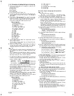
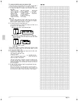
(Refer to figure 31)
1.
Meauring device
2.
R410A tank (with siphon)
3.
Charge hose
4.
Refrigerant charge port
5.
HP/LP gas pipe shutoff valve
6.
Suction gas pipe shutoff valve
7.
Liquid pipe shutoff valve
8.
Valve A
9.
Valve B
10.
Valve C
11.
Outdoor unit
12.
To BS, indoor unit
13.
Field pipings
14.
Refrigerant flow when charging
15.
Shutoff valve
16.
Service port
[Automatic refirgerant charging operation procedure]
Note
The marks of LED mean as follows.
h
: OFF
i
: ON
j
: Blinking
∗
: OFF, ON or Brinking
(1) Open the liquid pipe, suction gas pipe and HP/LP gas pipe shutoff
valves. (The valve A~C must be closed. See figure 31.)
(2) • Close the EL. COMPO. BOX (1) lid and all front panel except on
the EL. COMPO. BOX (1) side. (*1) And turn the power to the
outdoor unit and all connected BS, indoor units. (*2)
• After H2P stop blinking (about 12 minutes after turning on the
power), check H2P is OFF.
If H2P is ON, check the malfunction code in the remote control-
ler of indoor unit and correct the malfunction in accordance with
[Remote controller display malfunction code] in chapter 11-2-2.
(3) Check the LED. And push the MODE button (BS1) once if the LED
displays is not as below.
(4) Push the TEST button (BS4) once. (The LED displays will change
as below.)
(5) Hold the TEST button (BS4) down for 5 seconds or more.
(The LED displays will change as below and fan of outdoor unit
will start rotation.)
(6) When the compressor start working and the LED displays change
any state in below (*3), go to “In case of cooling mode” or “In case
of heating mode” in accordance with the LED displays.
In case of cooling mode
(7) Push the TEST button (BS4) once within 5 minutes after proce-
dure (5) (*4) and close the all front panels (*5).
After that, open the valve A immediately (See figure 31) (*6) and
watch the remote controller display of indoor unit.
(8) If the remote controller display shows “PE” code (*7), ready to
close the valve A.
And go to procedure (9).
If the remote controller display shows other code, close the valve
A immediately and refer to [Remote controller cooling mode mal-
function code]
Beware the fan running when open the front panel.
The fan may continue rotation after the system stop the operation.
(9) When the compressor stop working (the fan may continue rota-
tion.), close the valve A immediately (*8).
And check the LED displays are as below and the remote control-
ler display shows “P9” code.
After checking, push the MODE button (BS1) once and the charg-
ing is complete.
In case of heating mode
(7) Push the TEST button (BS4) once within 5 minutes after proce-
dure (5) (*4) and close the all front panels.
After that, open the valve A immediately (See figure 31) (*6) and
check the charged amount by meauring device.
During operation, if the remote controller display shows “P2” or
“P8” code, close the valve A immediately and refer to [Remote
controller heating mode malfunction code].
Outdoor temp. : 0˚C DB ~ 43˚C DB
Indoor temp. :
10˚C DB ~ 32˚C DB
Less than above range
Cooling mode
Heating mode
H1P H2P H3P H4P H5P H6P H7P
h
h
i
h
h
h
h
H1P H2P H3P H4P H5P H6P H7P
i i i i i i i
H1P H2P H3P H4P H5P H6P H7P
h
j
h
h
h
∗
∗
H1P H2P H3P H4P H5P H6P H7P
j j j
h
i
h
i
Go to “In case of
cooling mode”
j j
h
h
i
h
i
Go to “In case of
heating mode”
H1P H2P H3P H4P H5P H6P H7P
i j j i i i i
01_EN_3P201178-4B.fm Page 14 Friday, May 18, 2007 7:58 PM
Содержание VRV III REYQ10PY1B
Страница 6: ...3P201178 4B EM07A013 0705 HT ...
Страница 24: ...English 18 NOTES ...


