


Si37-701
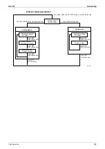
Field Setting
Test Operation
183
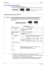
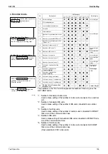
For setting items of (*1), refer to detailed information provided on page 191 onward.
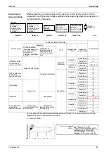
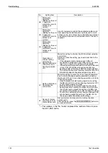
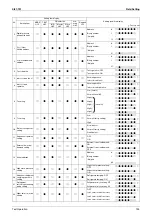
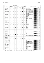
Setting item
Content and objective of setting
Overview of setting procedure
Reference
page
S
e
rv
ic
e s
e
tt
ing
1
Indoor unit
fan forced H
operation
Used to operate the indoor unit in the
stopped state in forced H operation
mode.
Set No. 5 of "Setting mode 2" to indoor
unit forced fan H.
2
Indoor unit
forced
operation
Used to operate the indoor unit in forced
operation mode.
Set No. 6 of "Setting mode 2" to indoor
unit forced operation mode.
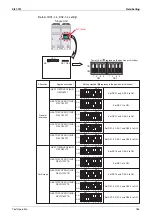
3
Change of
targeted
evaporating
temperature
(in cooling)
In cooling operation, used to change the
targeted evaporating temperature for
compressor capacity control.
Select high side or low side with No. 8 of
"Setting mode 2".
4
Change of
targeted
condensing
temperature
(in heating)
In heating operation, used to change the
targeted condensing temperature for
compressor capacity control.
Select high side or low side with No. 9 of
"Setting mode 2".
5
Setting of
defrost
selection
Used to change a temperature at which
the defrost operation is initiated, thus
making the initiation easy or hard.
Select fast side or slow side with No. 10 of
"Setting mode 2".
6
Setting of
sequential
startup
Used to start units not in sequence but
simultaneously.
Set No. 11 of "Setting mode 2" to NONE.
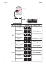
7
Emergency
operation (*1)
If the compressor has a failure, used to
prohibit the operation of outdoor unit(s)
concerned and to conduct emergency
operation of the system only with
operable or outdoor unit(s).
Make this setting while in "Setting mode
2".
For system with multiple outdoor units:
Set with No. 38, 39, or 40.
8
Additional
refrigerant
charging
If a necessary amount of refrigerant
cannot be charged due to the stop of
outdoor unit, operate the outdoor unit and
then refill refrigerant.
Set No. 20 of "Setting mode 2" to ON and
then charge refrigerant.
9
Refrigerant
recovery
mode (*1)
Used to recover refrigerant on site.
With operations of indoor and outdoor
units prohibited, open the outdoor/indoor
expansion valve fully while indoor/
outdoor operation is prohibited and turn
ON some of the solenoid valves.
Set No. 21 of "Setting mode 2" to ON.
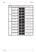
10
Vacuuming
mode (*1)
Used to conduct vacuuming on site.
Open the outdoor/indoor expansion valve
fully while indoor/outdoor operation is
prohibited and turn ON some of the
solenoid valves. Use a vacuum pump to
conduct vacuuming.
Set No. 21 of "Setting mode 2" to ON.
11
ENECUT test
operation
Used to forcedly turn ON the ENECUT.
(Be noted this mode is not functional with
the indoor unit remote controller turned
ON.)
Set No. 24 of "Setting mode 2" to ON.
12
Power
transistor
check mode
Used for the troubleshooting of DC
compressors.
Inverter waveform output makes it
possible to judge whether a malfunction
results from the compressor or the PC
board.
Set No. 28 of "Setting mode 2" to ON.
13
Setting of
model with
spare PC
board
In order to replace the PC board by a
spare one, be sure to make model setting.
For this setting, set the DS2-2, -3, and-4
switches on the PC board to the model
concerned.
Содержание VRV III REYQ10PY1
Страница 1: ...REYQ8 48PY1 R 410A Heat Recovery 50Hz Si37 701 ...
Страница 59: ...Specifications Si37 701 48 Specifications ...
Страница 105: ...Refrigerant Flow for Each Operation Mode Si37 701 94 Refrigerant Circuit ...
Страница 230: ...Si37 701 Troubleshooting by Remote Controller Troubleshooting 219 ...
Страница 373: ...Piping Diagrams Si37 701 362 Appendix 1 Piping Diagrams 1 1 Outdoor Unit REYQ8P 10P 12PY1 3D058154A S1NPH S2NPL ...
Страница 374: ...Si37 701 Piping Diagrams Appendix 363 REYQ14P 16PY1 3D058153A S2NPL S1NPH ...
Страница 375: ...Piping Diagrams Si37 701 364 Appendix REMQ8PY1 3D057743 ...
Страница 376: ...Si37 701 Piping Diagrams Appendix 365 REMQ10PY1 12PY1 3D057742 ...
Страница 377: ...Piping Diagrams Si37 701 366 Appendix REMQ14PY1 16PY1 3D057741 ...
Страница 382: ...Si37 701 Piping Diagrams Appendix 371 1 3 BS Unit 4D057985A ...
Страница 384: ...Si37 701 Wiring Diagrams for Reference Appendix 373 REYQ14 16PY1 3D056774C ...
Страница 385: ...Wiring Diagrams for Reference Si37 701 374 Appendix REMQ8PY1 3D055307E ...
Страница 386: ...Si37 701 Wiring Diagrams for Reference Appendix 375 REMQ10 12PY1 3D055308E ...
Страница 387: ...Wiring Diagrams for Reference Si37 701 376 Appendix REMQ14P 16PY1 3D055309E ...
Страница 388: ...Si37 701 Wiring Diagrams for Reference Appendix 377 2 2 Field Wiring REYQ8P 10P 12P 14P 16PY1 3D057764 ...
Страница 389: ...Wiring Diagrams for Reference Si37 701 378 Appendix REYQ18P 20P 22P 24P 26P 28P 30P 32PY1 3D057762 ...
Страница 390: ...Si37 701 Wiring Diagrams for Reference Appendix 379 REYQ34P 36P 38P 40P 42P 44P 46P 48PY1 3D057763 ...
Страница 391: ...Wiring Diagrams for Reference Si37 701 380 Appendix 2 3 Indoor Unit FXCQ20M 25M 32M 63MVE 3D039556A ...
Страница 392: ...Si37 701 Wiring Diagrams for Reference Appendix 381 FXCQ40M 50M 80M 125MVE 3D039557A ...
Страница 393: ...Wiring Diagrams for Reference Si37 701 382 Appendix FXFQ25M 32M 40M 50M 63M 80M 100M 125MVE 3D039600A ...
Страница 394: ...Si37 701 Wiring Diagrams for Reference Appendix 383 FXZQ20M 25M 32M 40M 50M8V1B 3D038359 ...
Страница 395: ...Wiring Diagrams for Reference Si37 701 384 Appendix FXKQ25MA 32MA 40MA 63MAVE 3D039564C ...
Страница 399: ...Wiring Diagrams for Reference Si37 701 388 Appendix FXDYQ180M 200M 250MV1 ...
Страница 400: ...Si37 701 Wiring Diagrams for Reference Appendix 389 FXSQ20M 25M 32M 40M 50M 63M 80M 100M 125MVE 3D039561B ...
Страница 401: ...Wiring Diagrams for Reference Si37 701 390 Appendix FXMQ40MA 50MA 63MA 80MA 100MA 125MAVE 3D039620B ...
Страница 402: ...Si37 701 Wiring Diagrams for Reference Appendix 391 FXMQ200MA 250MAVE 3D039621B ...
Страница 403: ...Wiring Diagrams for Reference Si37 701 392 Appendix FXHQ32MA 63MA 100MAVE 3D039801D ...
Страница 404: ...Si37 701 Wiring Diagrams for Reference Appendix 393 FXAQ20MA 25MA 32MAVE 40MA 50MA 63MAVE 3D034206D ...
Страница 406: ...Si37 701 Wiring Diagrams for Reference Appendix 395 2 4 BS Unit 3D055928C ...
Страница 423: ...Piping Installation Point Si37 701 412 Appendix ...
Страница 427: ...Example of Connection R 410A Type Si37 701 416 Appendix ...
Страница 433: ...Method of Checking the Inverter s Power Transistors and Diode Modules Si37 701 422 Appendix ...
Страница 447: ...Si37 701 iv Index ...
Страница 451: ...Si37 701 viii Drawings Flow Charts ...


