


Field Setting
Si37-701
194
Test Operation
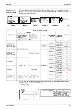
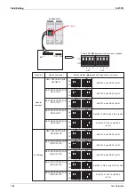
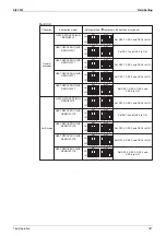
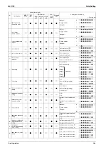
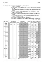
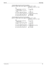
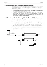
No.
Setting item display
Setting condition display
Setting item
MODE
H1P
TEST
H2P
C/H selection
Low
noise
H6P
Demand
H7P
IND
H3P
Master
H4P
Slave
H5P
∗
Factory set
24
ENECUT test
operation (Domestic
Japan only)
8
7
8
8
7
7
7
ENECUT output OFF
8777778
∗
ENECUT output forced ON
8777787
25 Low noise setting
8
7
8
8
7
7
8
Level 1 (outdoor fan with 6 step or lower)
8777778
Level 2 (outdoor fan with 5 step or lower)
8777787
∗
Level 3 (outdoor fan with 4 step or lower)
8777877
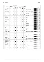
26
Night-time low noise
operation start
setting
8
7
8
8
7
8
7
About 20:00
8777778
About 22:00 (factory setting)
8777787
∗
About 24:00
8777877
27
Night-time low noise
operation end
setting
8
7
8
8
7
8
8
About 6:00
8777778
About 7:00
8777787
About 8:00 (factory setting)
8777877
∗
28
Power transistor
check mode
8
7
8
8
8
7
7
OFF
8777778
∗
ON
8777787
29
Capacity
precedence setting
8
7
8
8
8
7
8
OFF
8777778
∗
ON
8777787
30 Demand setting 1
8
7
8
8
8
8
7
60 % demand
8777778
70 % demand
8777787
∗
80 % demand
8777877
32
Normal demand
setting
8
8
7
7
7
7
7
OFF
8777778
∗
Demand 1
8777787
Demand 2
8777877
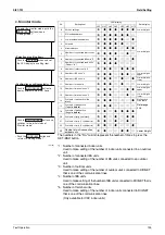
38
Emergency
operation
(Master unit is
inhibited to operate.)
8
8
7
7
8
8
7
OFF
8777778
∗
Master unit operation: Inhibited
8777787
39
Emergency
operation
(Slave unit 1 is
inhibited to operate.)
8
8
7
7
8
8
8
OFF
8777778
∗
Slave unit 1 operation: Inhibited
8777787
40
Emergency
operation
(Slave unit 2 is
inhibited to operate.)
8
8
7
8
7
7
7
OFF
8777778
∗
Slave unit 2 operation: Inhibited
8777787
41
Prevention of minute
heating operation by
heating thermostat
OFF unit or non-
heating-operation
unit
8
8
7
8
7
7
8
OFF
8777777
Non-heating-operation unit
8777778
Heating thermostat OFF unit
8777787
Non-heating-ope Thermostat OFF unit
8777788
∗
42
Setting of BS Cool-
Heat selection
control time
8
8
7
8
7
8
7
6 min.
8777777
∗
4 min.
8777778
51
Master-slave set-up
for multi outdoor
units
8
8
8
7
7
8
8
Automatic judgment
8777777
∗
Master
8777778
Slave 1
8777787
Slave 2
8777788
The numbers in the "No." column represent the number of times to press the SET (BS2) button.
Содержание VRV III REYQ10PY1
Страница 1: ...REYQ8 48PY1 R 410A Heat Recovery 50Hz Si37 701 ...
Страница 59: ...Specifications Si37 701 48 Specifications ...
Страница 105: ...Refrigerant Flow for Each Operation Mode Si37 701 94 Refrigerant Circuit ...
Страница 230: ...Si37 701 Troubleshooting by Remote Controller Troubleshooting 219 ...
Страница 373: ...Piping Diagrams Si37 701 362 Appendix 1 Piping Diagrams 1 1 Outdoor Unit REYQ8P 10P 12PY1 3D058154A S1NPH S2NPL ...
Страница 374: ...Si37 701 Piping Diagrams Appendix 363 REYQ14P 16PY1 3D058153A S2NPL S1NPH ...
Страница 375: ...Piping Diagrams Si37 701 364 Appendix REMQ8PY1 3D057743 ...
Страница 376: ...Si37 701 Piping Diagrams Appendix 365 REMQ10PY1 12PY1 3D057742 ...
Страница 377: ...Piping Diagrams Si37 701 366 Appendix REMQ14PY1 16PY1 3D057741 ...
Страница 382: ...Si37 701 Piping Diagrams Appendix 371 1 3 BS Unit 4D057985A ...
Страница 384: ...Si37 701 Wiring Diagrams for Reference Appendix 373 REYQ14 16PY1 3D056774C ...
Страница 385: ...Wiring Diagrams for Reference Si37 701 374 Appendix REMQ8PY1 3D055307E ...
Страница 386: ...Si37 701 Wiring Diagrams for Reference Appendix 375 REMQ10 12PY1 3D055308E ...
Страница 387: ...Wiring Diagrams for Reference Si37 701 376 Appendix REMQ14P 16PY1 3D055309E ...
Страница 388: ...Si37 701 Wiring Diagrams for Reference Appendix 377 2 2 Field Wiring REYQ8P 10P 12P 14P 16PY1 3D057764 ...
Страница 389: ...Wiring Diagrams for Reference Si37 701 378 Appendix REYQ18P 20P 22P 24P 26P 28P 30P 32PY1 3D057762 ...
Страница 390: ...Si37 701 Wiring Diagrams for Reference Appendix 379 REYQ34P 36P 38P 40P 42P 44P 46P 48PY1 3D057763 ...
Страница 391: ...Wiring Diagrams for Reference Si37 701 380 Appendix 2 3 Indoor Unit FXCQ20M 25M 32M 63MVE 3D039556A ...
Страница 392: ...Si37 701 Wiring Diagrams for Reference Appendix 381 FXCQ40M 50M 80M 125MVE 3D039557A ...
Страница 393: ...Wiring Diagrams for Reference Si37 701 382 Appendix FXFQ25M 32M 40M 50M 63M 80M 100M 125MVE 3D039600A ...
Страница 394: ...Si37 701 Wiring Diagrams for Reference Appendix 383 FXZQ20M 25M 32M 40M 50M8V1B 3D038359 ...
Страница 395: ...Wiring Diagrams for Reference Si37 701 384 Appendix FXKQ25MA 32MA 40MA 63MAVE 3D039564C ...
Страница 399: ...Wiring Diagrams for Reference Si37 701 388 Appendix FXDYQ180M 200M 250MV1 ...
Страница 400: ...Si37 701 Wiring Diagrams for Reference Appendix 389 FXSQ20M 25M 32M 40M 50M 63M 80M 100M 125MVE 3D039561B ...
Страница 401: ...Wiring Diagrams for Reference Si37 701 390 Appendix FXMQ40MA 50MA 63MA 80MA 100MA 125MAVE 3D039620B ...
Страница 402: ...Si37 701 Wiring Diagrams for Reference Appendix 391 FXMQ200MA 250MAVE 3D039621B ...
Страница 403: ...Wiring Diagrams for Reference Si37 701 392 Appendix FXHQ32MA 63MA 100MAVE 3D039801D ...
Страница 404: ...Si37 701 Wiring Diagrams for Reference Appendix 393 FXAQ20MA 25MA 32MAVE 40MA 50MA 63MAVE 3D034206D ...
Страница 406: ...Si37 701 Wiring Diagrams for Reference Appendix 395 2 4 BS Unit 3D055928C ...
Страница 423: ...Piping Installation Point Si37 701 412 Appendix ...
Страница 427: ...Example of Connection R 410A Type Si37 701 416 Appendix ...
Страница 433: ...Method of Checking the Inverter s Power Transistors and Diode Modules Si37 701 422 Appendix ...
Страница 447: ...Si37 701 iv Index ...
Страница 451: ...Si37 701 viii Drawings Flow Charts ...


