


Field Setting
Si37-701
188
Test Operation
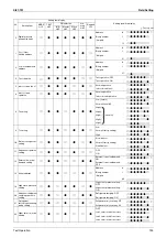
3.2.3 Setting by Push Button Switches
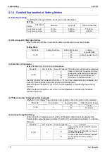
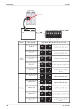
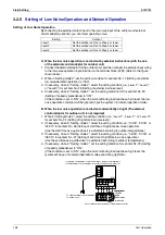
The following settings are made by push button switches on PC board.
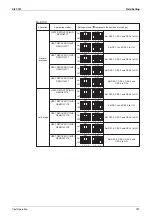
In case of multi-outdoor unit system, various items should be set with the master unit.
(Setting with the slave unit is disabled.)
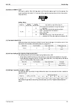
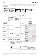
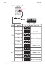
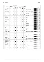
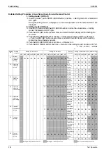
The master unit and slave unit can be discriminated with the LED display as shown below.
(Factory setting)
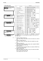
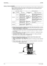
There are the following three setting modes.
c
Setting mode 1 (H1P off)
Initial status (when normal) : Used to select the cool/heat setting. Also indicates during
“abnormal”, “low noise control” and “demand control”.
d
Setting mode 2 (H1P on)
Used to modify the operating status and to set program addresses, etc. Usually used in
servicing the system.
e
Monitor mode (H1P blinks)
Used to check the program made in Setting mode 2.
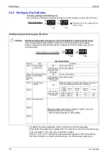
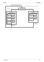
Mode changing procedure 1
LED display
MODE
H1P
TEST
H2P
COOL/HEAT select
Low
noise
H6P
Demand
H7P
Multi;
H8P
IND
H3P
MASTER
H4P
SLAVE
H5P
Single-outdoor-unit
system
7
7
8
7
7
7
7
7
Outdoor-
multi
system
Master
7
7
8
7
7
7
7
8
Slave 1
7
7
7
7
7
7
7
9
Slave 2
7
7
7
7
7
7
7
7
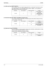
Pushbutton switches
Used to change
the setting mode
Used for
onsite setting
Used to set up address
when wiring is changed
or an indoor unit is added
Used for check operation and
test operation
MODE
SET
RETURN
TEST
BS1
BS2
BS3
BS4
BS5
REWIRING
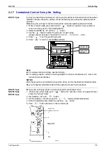
Setting mode 1
Monitor mode
H1P
Push the BS1(MODE button)
one time.
Blinking
MODE
MODE
Off
H1P
Setting mode 2
MODE
On
H1P
Push and hold the BS1
(MODE button) for 5 seconds.
Push the BS1(MODE button) one time.
(Normal)
(V2761)
Using the MODE button, the modes can be changed as follows.
Содержание VRV III REYQ10PY1
Страница 1: ...REYQ8 48PY1 R 410A Heat Recovery 50Hz Si37 701 ...
Страница 59: ...Specifications Si37 701 48 Specifications ...
Страница 105: ...Refrigerant Flow for Each Operation Mode Si37 701 94 Refrigerant Circuit ...
Страница 230: ...Si37 701 Troubleshooting by Remote Controller Troubleshooting 219 ...
Страница 373: ...Piping Diagrams Si37 701 362 Appendix 1 Piping Diagrams 1 1 Outdoor Unit REYQ8P 10P 12PY1 3D058154A S1NPH S2NPL ...
Страница 374: ...Si37 701 Piping Diagrams Appendix 363 REYQ14P 16PY1 3D058153A S2NPL S1NPH ...
Страница 375: ...Piping Diagrams Si37 701 364 Appendix REMQ8PY1 3D057743 ...
Страница 376: ...Si37 701 Piping Diagrams Appendix 365 REMQ10PY1 12PY1 3D057742 ...
Страница 377: ...Piping Diagrams Si37 701 366 Appendix REMQ14PY1 16PY1 3D057741 ...
Страница 382: ...Si37 701 Piping Diagrams Appendix 371 1 3 BS Unit 4D057985A ...
Страница 384: ...Si37 701 Wiring Diagrams for Reference Appendix 373 REYQ14 16PY1 3D056774C ...
Страница 385: ...Wiring Diagrams for Reference Si37 701 374 Appendix REMQ8PY1 3D055307E ...
Страница 386: ...Si37 701 Wiring Diagrams for Reference Appendix 375 REMQ10 12PY1 3D055308E ...
Страница 387: ...Wiring Diagrams for Reference Si37 701 376 Appendix REMQ14P 16PY1 3D055309E ...
Страница 388: ...Si37 701 Wiring Diagrams for Reference Appendix 377 2 2 Field Wiring REYQ8P 10P 12P 14P 16PY1 3D057764 ...
Страница 389: ...Wiring Diagrams for Reference Si37 701 378 Appendix REYQ18P 20P 22P 24P 26P 28P 30P 32PY1 3D057762 ...
Страница 390: ...Si37 701 Wiring Diagrams for Reference Appendix 379 REYQ34P 36P 38P 40P 42P 44P 46P 48PY1 3D057763 ...
Страница 391: ...Wiring Diagrams for Reference Si37 701 380 Appendix 2 3 Indoor Unit FXCQ20M 25M 32M 63MVE 3D039556A ...
Страница 392: ...Si37 701 Wiring Diagrams for Reference Appendix 381 FXCQ40M 50M 80M 125MVE 3D039557A ...
Страница 393: ...Wiring Diagrams for Reference Si37 701 382 Appendix FXFQ25M 32M 40M 50M 63M 80M 100M 125MVE 3D039600A ...
Страница 394: ...Si37 701 Wiring Diagrams for Reference Appendix 383 FXZQ20M 25M 32M 40M 50M8V1B 3D038359 ...
Страница 395: ...Wiring Diagrams for Reference Si37 701 384 Appendix FXKQ25MA 32MA 40MA 63MAVE 3D039564C ...
Страница 399: ...Wiring Diagrams for Reference Si37 701 388 Appendix FXDYQ180M 200M 250MV1 ...
Страница 400: ...Si37 701 Wiring Diagrams for Reference Appendix 389 FXSQ20M 25M 32M 40M 50M 63M 80M 100M 125MVE 3D039561B ...
Страница 401: ...Wiring Diagrams for Reference Si37 701 390 Appendix FXMQ40MA 50MA 63MA 80MA 100MA 125MAVE 3D039620B ...
Страница 402: ...Si37 701 Wiring Diagrams for Reference Appendix 391 FXMQ200MA 250MAVE 3D039621B ...
Страница 403: ...Wiring Diagrams for Reference Si37 701 392 Appendix FXHQ32MA 63MA 100MAVE 3D039801D ...
Страница 404: ...Si37 701 Wiring Diagrams for Reference Appendix 393 FXAQ20MA 25MA 32MAVE 40MA 50MA 63MAVE 3D034206D ...
Страница 406: ...Si37 701 Wiring Diagrams for Reference Appendix 395 2 4 BS Unit 3D055928C ...
Страница 423: ...Piping Installation Point Si37 701 412 Appendix ...
Страница 427: ...Example of Connection R 410A Type Si37 701 416 Appendix ...
Страница 433: ...Method of Checking the Inverter s Power Transistors and Diode Modules Si37 701 422 Appendix ...
Страница 447: ...Si37 701 iv Index ...
Страница 451: ...Si37 701 viii Drawings Flow Charts ...


