


Installation manual
25
REMQ8~16P8Y1B
VRVIII System air conditioner
4PW40598-1A
12.4. Test operation
■
In case the unit is operated with the leak detection function
available:
■
the outdoor temperature must be 0°C DB~43°C DB
■
the indoor temperature must be 20°C DB~32°C DB
In case the unit is operated out of the temperature range as
instructed above, the display of the remote controller shows
U3
and the unit operates without the availability of the leak detection
function.
■
In the test operation, the following checks and judgement will be
performed:
■
Check of the stop valve opening
■
Check for wrong wiring
■
Check of refrigerant overcharge
■
Initial refrigerant detection
■
In case the leak detection function is available, the check
operation will last 2 hours, otherwise it takes between 40 and
60 minutes to complete the check operation.
■
Make sure to carry out the test operation after the first
installation. Otherwise, the malfunction code
U3
will be displayed
on the remote controller and normal operation can not be
carried out.
■
In case of a multi system, check the settings and results on the
master unit.
■
Abnormalities on indoor units can not be checked for each unit
individual. After the test operation is finished, check the indoor
units one by one by performing a normal operation using the
remote controller.
Test operation procedure
1
Close all front panels except the front panel of the electric box.
2
Turn ON the power to all outdoor units and the connected indoor
units.
Be sure to turn on the power 6 hours before operation in order to
have power running to the crank case heater and to protect the
compressor.
3
Make the field setting as described in the paragraph
4
Press the
button once, and set to the SETTING
MODE (H1P LED = OFF).
5
In case the leak detection function is required,
press and hold the
button down for 5 seconds or
more. The unit will start the test operation.
In case the leak detection function is not required,
go into setting mode 2 by pressing the
button for 5
seconds. The H1P LED is on
w
. Perform following steps.
1.
Press the
button 3 times.
2.
Press the
button once to confirm.
3.
Press the
button in order to change the LED
display to the following display.
4.
Press the
button once to confirm.
5.
Press the
button a second time to start the
test operation. The unit will start the test operation.
■
The test operation is automatically carried out in cooling
mode, the H2P LED will light up and the messages "Test
operation" and "Under centralized control" will display on the
remote controller.
■
It may take 10 minutes to bring the state of the refrigerant
uniform before the compressor starts.
■
During the test operation, the refrigerant running sound or
the magnetic sound of a solenoid valve may become loud
and the LED display may change, but these are not mal-
functions.
■
During the test operation, it is not possible to stop the unit
operation from a remote controller. To abort the operation,
press the
button. The unit will stop after
±30 seconds.
6
Close the front panel in order to let it not be the cause of
misjudgement.
7
Check the test operation results by the LED display on the
outdoor unit.
8
When the test operation is fully completed, normal operation will
be possible after 5 minutes.
Otherwise, refer to
"Correcting after abnormal completion of the
to take actions for correcting the
abnormality.
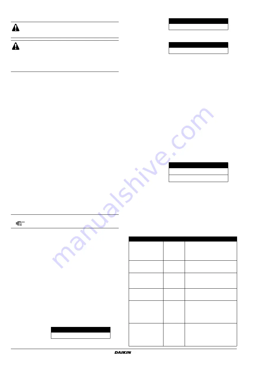
Correcting after abnormal completion of the test operation
The test operation is only completed if there is no malfunction code
displayed on the remote controller. In case of a displayed malfunction
code, perform the following actions to correct the abnormality:
■
Confirm the malfunction code on the remote controller
Do not insert fingers, rods or other objects into the air
inlet or outlet. When the fan is rotating at high speed, it
will cause injury.
Do not perform the test operation while working on the
indoor units.
When performing the test operation, not only the outdoor
unit, but the connected indoor unit will operate as well.
Working on a indoor unit while performing a test operation
is dangerous.
NOTE
A test operation can not be carried out when the
outdoor temperature is less than –5°C.
H1P
H2P
H3P
H4P
H5P
H6P
H7P
w x
x
x
x w w
BS1 MODE
BS4 TEST
BS1 MODE
BS2 SET
H1P
H2P
H3P
H4P
H5P
H6P
H7P
w x
x
x
x
x c
H1P
H2P
H3P
H4P
H5P
H6P
H7P
w x
x
x
x c x
H1P
H2P
H3P
H4P
H5P
H6P
H7P
Normal completion
x
x w x
x
x
x
Abnormal completion
x w w x
x
x
x
Installation error
Error code
Remedial action
The stop valve of an
outdoor unit is left
closed.
E3
E4
F3
F6
UF
Open the stop valve.
The phases of the
power to the outdoor
units are reversed.
U1
Exchange two of the three phases
(L1, L2, L3) to make a positive
phase connection.
No power is supplied
to an outdoor or
indoor unit (including
phase interruption).
LC
U1
U4
Check if the power wiring for the
outdoor units are connected
correctly.
Incorrect
interconnections
between units
UF
Check if the refrigerant line piping
and the unit wiring are consistent
with each other.
Refrigerant
overcharge
E3
F6
UF
Recalculate the required amount of
refrigerant from the piping length
and correct the refrigerant charge
level by recovering any excessive
refrigerant with a refrigerant
recovery machine.
Insufficient refrigerant
E4
F3
Check if the additional refrigerant
charge has been finished correctly.
Recalculate the required amount of
refrigerant from the piping length
and add an adequate amount of
refrigerant.
BS3 RETURN
BS2 SET
BS3 RETURN
BS3 RETURN
BS3 RETURN