

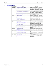


Troubleshooting
Si71-502
42
Troubleshooting
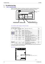
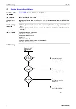
1.7
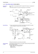
Damper System Error (Alarm)
Remote Controller
LCD Display
Error Code
6A
Inspection Blinking Unit No. Blinking
LED Indication
Remote Controller
5
Main Unit
5
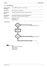
Error Detection
Method
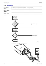
Measurement of damper motor limit switch ON/OFF time and temperatures detected by outdoor and indoor
air thermistor.
Error Generating
Conditions
When damper system error (alarm) and indoor (or outdoor) thermistor error are generated at the same
time.
When damper system error (alarm) occurs and values of indoor and outdoor air thermistor meet frost
conditions.
Possible Causes
Faulty damper motor or limit switch
Faulty indoor air thermistor
Faulty outdoor air thermistor
Frosting
Broken wire in cable
Faulty contact in connector (including relay connector)
Faulty control PCB assembly
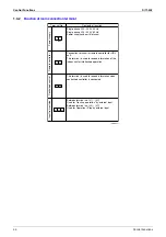
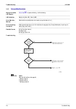
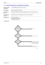
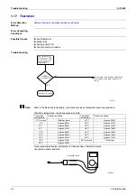
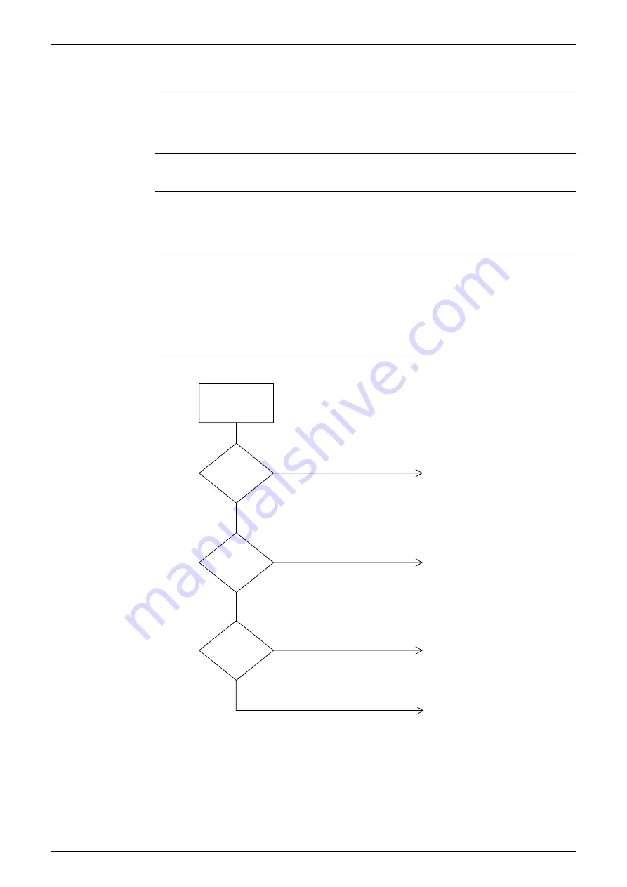
Troubleshooting
Check error record on
malfunction history
display in service
mode.
Is "64" recorded?
YES
YES
YES
Take corrective measures
specified for damper system
error (alarm).
(Remove the cause of problem,
and reset display.)
Take corrective measures
specified for damper system
error (alarm) and indoor and
outdoor air thermistor errors.
Take corrective measures
specified for damper system
error (alarm) and outdoor air
thermistor error.
Take corrective measures
specified for damper system
error (alarm) and indoor and
outdoor air thermistor error.
Are
"6A" and "64"
or "65" recorded?
NO
(HF006)
NO
Are
"64" and "65"
recorded?
NO
Содержание VAM 350GJVE
Страница 7: ...Introduction Si71 502 vi 1 1 1 Cautions in Operation and Maintenance...
Страница 8: ...Si71 502 Introduction vii...
Страница 13: ...General Constructions Si71 502 4 General Constructions...
Страница 29: ...Maintenance Si71 502 20 Maintenance...
Страница 43: ...Circuit Operations Si71 502 34 Circuit Operations...
Страница 103: ...After sales Service Si71 502 94 Operation Manual...
Страница 106: ...Si71 502 Appendix Appendix 97 VAM1500GJVE VAM2000GJVE...
Страница 107: ...Appendix Si71 502 98 Appendix...