


11
See the “Service Precautions” label on the back of the front panel for the
settings for operation after replenishing refrigerant.
1. Open the gas line stop valve (leaving the liquid line stop valve, valve
A in the diagram above, close) and perform the operation to add the
refrigerant.
2. Once the appropriate amount of refrigerant is in, press the confirma-
tion button (BS3) on the outdoor unit PC board (A1P), and stop oper-
ation.
3. Open the stop valves quickly (both liquid and gas line valves).
(This must be done quickly to avoid the possibility that the pipe might
burst.)
• The figure below shows the name of each part required in handling the
stop valve. At the time of shipment, the stop valve is closed.
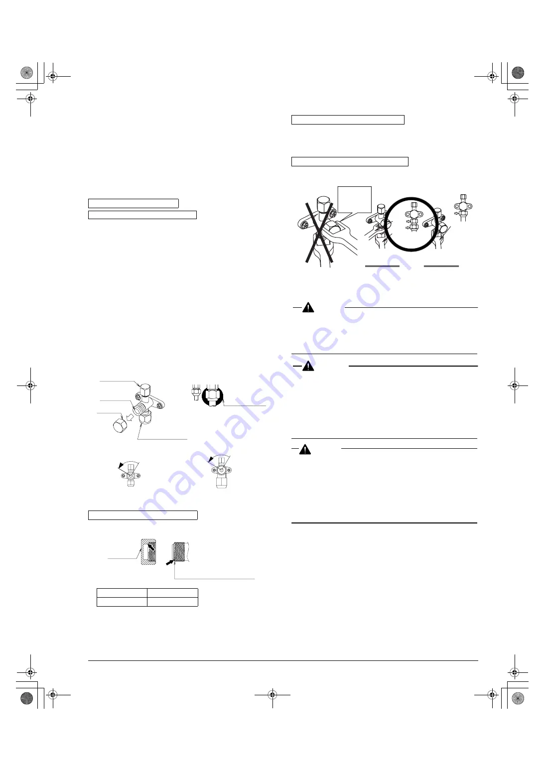
• If only a torque wrench is used to loosen or tighten the flare nut, the
side plate may be distorted. Make sure to fix the stop valve with a
spanner, then loosen or tighten the flare nut with a torque wrench.
• When it is expected that the operating pressure will be low (for
example, when cooling will be performed while the outside air tem-
perature is low), seal sufficiently the flare nut in the stop valve on the
gas line with silicon sealant to prevent freezing.
[Stop valve operation method]
Prepare hexagon wrenches (whose size is 4 mm and 6 mm).
How to open the stop valve
1. Insert a hexagon wrench into the valve stem, and turn the
valve stem counterclockwise.
2. When the valve stem cannot be turned any more, stop turning.
Now, the valve is open.
How to close the stop valve
1. Insert a hexagon wrench into the valve stem, and turn the
valve stem clockwise.
2. When the valve stem cannot be turned any more, stop turning.
Now, the valve is closed.
• The valve is sealed in the arrow area. Take care not to damage the
arrow area.
• After handling the valve, make sure to tighten the valve cap securely.
• Use charge hose equipped with push in the work.
• After the work, make sure to tighten the valve cap securely.
Tightening torque.....8.5~10.3 ft·lbf
Using a spanner on the valve cap and the valve body could cause a
refrigerant leak.
7. ELECTRIC WIRING WORK
DANGER
• Do not ground units to water pipes, telephone wires or lightning rods
because incomplete grounding could cause a severe shock hazard
resulting in severe injury or death, and to gas pipes because a gas
leak could result in an explosion which could lead to severe injury or
death.
WARNING
• Disconnect all power to unit to avoid possible electric shock
during installation.
• Use only specified wire and connect wires to terminals tightly. Be
careful that wires do not place external stress on terminals. Keep
wires in neat order so as to not to obstruct other equipment. Incom-
plete connections could result in overheating, and in worse cases,
electric shock or fire.
For the details, refer to
“7-3 Power supply wiring connection proce-
dure”
.
CAUTION
<To electrician>
• Do not operate the air conditioner until the refrigerant piping work is
completed.
(Operating the air conditioner before the refrigerant piping work is
completed may damage the compressor.)
• Install an earth leakage circuit breaker.
(The inverter is provided in the air conditioner. In order to prevent
malfunction of the earth leakage circuit breaker itself, use a breaker
resistant to higher harmonics.)
• Electricians having sufficient knowledge should perform the electri-
cal wiring work.
All wiring must comply with local electrical codes and National Elec-
trical Code (NEC).
• Perform the electric wiring work in accordance with the “electric wir-
ing diagram label”.
Make sure to turn OFF the branch switch and overcurrent breaker
before starting the work.
• Perform grounding to the indoor units and outdoor units.
• Use only copper wires.
• Make sure to turn the power off before starting the electric wiring
work.
Do not turn ON any switch until the work is completed.
Stop valve operation method
Cautions on handling the stop valve
Cautions on handling the valve cap
Liquid line
Gas line
10.0~12.2 ft·lbf
16.6~20.3 ft·lbf
Valve cap
Service port
Field piping
connection part
Valve stem
Silicon sealant
(Take care not to generate cavity.)
<Liquid line>
<Gas line>
Opening direction
Opening direction
Valve cap
Stop valve
(valve cap attachment area)
Cautions on handling the service port
Do not apply any force to the valve cap.
Spanner
prohibition to
valve cap and
body part
Stop valve of two
hangs stucture
Stop valve of one
hangs stucture
Torque
wrench
Torque
wrench
Spanner
01_EN_3PN05597-5R.fm Page 11 Wednesday, September 14, 2005 8:35 PM