background image

5 Installation

Installation and operation manual

10

RXYSQ6T8Y1B9

VRV IV-S system air conditioner

4P482276-1 – 2017.04

3

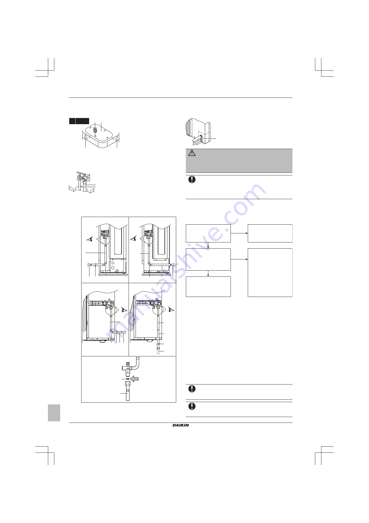
If you have chosen the downwards piping route:

▪ Drill (a, 4×) and remove the knockout hole (b).
▪ Cut out the slits (c) with a metal saw.

c

c

b

a

4× Ø6 mm

4

Do the following:

▪ Connect the liquid pipe (a) to the liquid stop valve.
▪ Connect the gas pipe (b) to the gas stop valve.

a

b

▪ Connect  the  gas  piping  accessories  (c,  c1,  d,  e),  and  cut

them to the required length (e1). This is necessary because
the  size  of  the  gas  stop  valve  is  Ø15.9  while  the  piping
between outdoor unit and first refrigerant branch kit is Ø19.1.

Possibility 1: To the front

A

e1 e

c

d

f

Possibility 2: To the back

A

c

d

e

f

Possibility 3: To the side

A

c

d e1 e f

Possibility 4: Downwards

A

c

e1
f

e

A

c1

c

c, c1

Gas piping accessory 1 + copper gasket (always use it)

d

Gas piping accessory 2

e, e1

Gas piping accessory 3 (cut it to the required length)

f

Field supply

5

Reattach the service cover and the piping intake plate.

6

Seal  all  gaps  (example:  a)  to  prevent  snow  and  small  animals
from entering the system.

a

WARNING

Provide adequate measures to prevent that the unit can be
used  as  a  shelter  by  small  animals.  Small  animals  that
make contact with electrical parts can cause malfunctions,
smoke or fire.

NOTICE

Make  sure  to  open  the  stop  valves  after  installing  the
refrigerant  piping  and  performing  vacuum  drying.  Running
the  system  with  the  stop  valves  closed  may  break  the
compressor.

5.4

Checking the refrigerant piping

5.4.1

About checking the refrigerant piping

Refrigerant piping works are 

finished?

The indoor units and/or 

outdoor unit were already 

powered ON?

Use procedure:
"Method 2: After power ON".

Finish piping work.

Use procedure:
"Method 1: Before power ON 

(regular method)".

Yes

No

No

Yes

It is very important that all refrigerant piping work is done before the
units (outdoor or indoor) are powered on.

When the units are powered on, the expansion valves will initialise.
This means that they will close. Leak test and vacuum drying of field
piping and indoor units is impossible when this happens.

Therefore,  there  will  be  explained  2  methods  for  initial  installation,
leak test and vacuum drying.

Method 1: Before power ON

If  the  system  has  not  yet  been  powered  on,  no  special  action  is
required to perform the leak test and the vacuum drying.

Method 2: After power ON

If  the  system  has  already  been  powered  on,  activate  setting  [2‑21]
(refer  to 

"6.1.4  To  access  mode  1  or  2"  on  page  17

).  This  setting

will  open  field  expansion  valves  to  guarantee  a  R410A  piping
pathway  and  make  it  possible  to  perform  the  leak  test  and  the
vacuum drying.

NOTICE

Make  sure  that  all  indoor  units  connected  to  the  outdoor
unit are powered on.

NOTICE

Wait  until  the  outdoor  unit  has  finished  the  initialisation  to
apply setting [2‑21].

Содержание RXYSQ6T8Y1B9

Страница 1: ...Installation and operation manual VRV IV S system air conditioner English Installation and operation manual VRV IV S system air conditioner RXYSQ6T8Y1B9...

Страница 2: ...1700 1000 500 HU a b 100 100 c d e eB eD A B C D E HB HD A B C 200 300 1000 A B C E 200 300 1000 1000 500 D 1000 D E 1000 1000 500 B D HD HU 300 1000 HD HU 250 1500 HU HD HU 300 1500 B D E HB HD HB H...

Страница 3: ...ogojem da se uporabljajo v skladu z na imi navodili on vastavuses j rgmis t e standardi te ga v i teiste normatiivsete dokumentidega kui neid kasutatakse vastavalt meie juhenditele atitinka emiau nuro...

Страница 4: ...ng the electrical wiring 14 5 7 4 To connect the electrical wiring on the outdoor unit 14 5 8 Finishing the outdoor unit installation 15 5 8 1 To finish the transmission wiring 15 6 Configuration 16 6...

Страница 5: ...nce Authorised installers end users INFORMATION This appliance is intended to be used by expert or trained users in shops in light industry and on farms or for commercial use by lay persons Documentat...

Страница 6: ...dity conditions make sure to take precautions to keep the drain holes of the unit free by using proper equipment In heating T AO C WB a b 20 15 5 15 10 5 0 5 10 15 20 10 15 20 2527 30 TAI C DB a Warmi...

Страница 7: ...Piping between refrigerant branch kit and indoor unit Use the same diameters as the connections liquid gas on the indoor units The diameters of the indoor units are as follows Indoor unit capacity ind...

Страница 8: ...To install the outdoor unit 4 M12 5 2 3 To provide drainage Make sure that condensation water can be evacuated properly Install the unit on a base to make sure that there is a proper drainage in orde...

Страница 9: ...alve is now closed Closing direction To handle the stop valve cover The stop valve cover is sealed where indicated by the arrow Do NOT damage it After handling the stop valve tighten the stop valve co...

Страница 10: ...open the stop valves after installing the refrigerant piping and performing vacuum drying Running the system with the stop valves closed may break the compressor 5 4 Checking the refrigerant piping 5...

Страница 11: ...fer to the indoor unit installation manual for more details Leak test and vacuum drying should be done before the power supply is set to the unit If not see also the flow chart earlier described in th...

Страница 12: ...e finished properly NOTICE Be sure to turn on the power 6 hours before operation in order to have power running to the crankcase heater and to protect the compressor NOTICE If operation is performed w...

Страница 13: ...y operating the outdoor unit by means of the manual additional refrigerant charge mode 5 Connect as shown Make sure valve A is closed p p R410A a c d b A d a Weighing scales b Refrigerant R410A tank s...

Страница 14: ...unit near the gas and liquid stop valves 5 7 Connecting the electrical wiring 5 7 1 Field wiring Overview Field wiring consists of power supply always including earth and indoor outdoor communication...

Страница 15: ...3 1 a Power supply cable b Transmission wiring cable Connecting to the frame When cables are routed from the unit a protection sleeve for the conduits PG insertions can be inserted at the knockout hol...

Страница 16: ...or special operation e g 1 time operation recovery vacuuming setting manual adding refrigerant setting etc In such a case it is required to abort the special operation before normal operation can rest...

Страница 17: ...iring Switching between modes Use BS1 to switch between the default situation mode 1 and mode 2 B S 1 5 s B S 1 B S 1 B S 1 a c b a Default situation H1P OFF b Mode 1 H1P flashing c Mode 2 H1P ON BS1...

Страница 18: ...an optional accessory is required Value Description H7P Shows the status of power consumption limitation operation OFF Unit is currently not operating under power consumption limitations ON Unit is c...

Страница 19: ...gerant charge amount in a manual way without automatic refrigerant charging functionality following setting should be applied default Deactivated Activated To stop the manual additional refrigerant ch...

Страница 20: ...al signal is sent to the unit this setting defines the level power consumption limitation that will be applied for step 1 The level is according to the table 60 default 70 80 2 31 Power consumption li...

Страница 21: ...t correspond to the voltage on the identification label of the unit Earth wiring Be sure that the earth wires have been connected properly and that the earth terminals are tightened Insulation test of...

Страница 22: ...Under centralised control will display on the user interface of indoor units Steps during the automatic system test run procedure Step Description Control before start up pressure equalisation Coolin...

Страница 23: ...Suction temperature sensor malfunction R3T A1P X12A R5T A1P X12A Check connection on PCB or actuator Liquid temperature sensor coil malfunction R4T A1P X12A Check connection on PCB or actuator Liquid...

Страница 24: ...allowed Multiple rows of units See figure 2 on the inside of the front cover Stacked units max 2 levels See figure 3 on the inside of the front cover A1 A2 A1 If there is danger of drainage dripping...

Страница 25: ...2P Printed circuit board inverter BS Push buttons mode set return test reset A1P C Capacitor A2P DS1 DIP switch A1P F1U F2U Fuse T 31 5 A 500 V A1P F1U Fuse T 5 0 A 250 V A2P F3U F4U F5U Fuse T 6 3 A...

Страница 26: ...ay be put in action and the air conditioner may not operate Above operation range is only valid in case direct expansion indoor units are connected to the VRV IV S system 12 2 Operating the system 12...

Страница 27: ...emperature decrease minimal room cooling The micro computer automatically determines temperature and fan speed cannot be set by the user interface The system does not go into operation if the room tem...

Страница 28: ...essary to designate one of the user interfaces as the master user interface The displays of slave user interfaces show change over under centralised control and slave user interfaces automatically fol...

Страница 29: ...s gas cookers etc is present Always have qualified service personnel confirm that the point of leakage has been repaired or corrected before resuming operation 14 Troubleshooting If one of the followi...

Страница 30: ...over current detected Main code Contents Compressor lock startup Transmission outdoor unit inverter INV transmission trouble INV unbalanced power supply voltage Fin thermistor malfunction Capacity se...

Страница 31: ...ystem stops after heating operation Expansion and contraction of plastic parts caused by temperature change make this noise A low sah choro choro sound is heard while the indoor unit is stopped When a...

Страница 32: ...4P482276 1 2017 04 Copyright 2017 Daikin 4P482276 1 0000000R...

Отзывы: