


SiUS371901E
Field Settings for Indoor Unit
Field Settings and Test Operation
172
Note that the control is automatically switched to the one performed only by the suction air thermistor for indoor
unit when the Second code No. is
01
during group control.
To use the
remote controller thermostat control during group control
, select the Second code No.
02
in First
code No.
6
.
Note:
When the 10 (20)-6 setting is changed to
02
, several indoor units are controlled by one remote
controller thermistor, so note that the room temperature might be uneven.
Filter Cleaning Sign
Whether or not to display "Filter Cleaning" after operation of certain duration can be selected.
∗
Filter cleaning sign is not displayed when an Auto-clean Panel is connected.
Information for intelligent Touch Manager / intelligent Touch Controller
∗
When field setting 10 (20)-6-
02
is set at the same time as 10 (20)-2-
01,02,03,
field setting 10 (20)-2 has priority.
When field setting 10 (20)-6-
01
is set at the same time as 10 (20)-2-
01,02,03,
field setting 10 (20)-6 has priority
for group connection, and 10 (20)-2 has priority for individual connection.
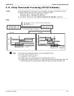
Time for Absence Area Detection
(For units with an infrared presence/floor sensor only)
By selecting the energy-saving operation mode in the absence, the target temperature is shifted to the energy-
saving end by 1°C (1.8°F) (maximum 2°C (3.6°F)) after the state of absence continues for a certain period of time.
Absent time defined for detection can be selected as follows:
• The set temperature displayed on the remote controller remains same even if the target temperature is shifted.
• As soon as people is detected while the temperature is shifted, this control will be cancelled (reset).
Mode No.
First Code No. Second Code No.
Contents
10 (20)
6
01
Remote controller thermostat control is not permitted during group control.
02
Remote controller thermostat control is permitted during group control.
Mode No.
First Code No.
Second Code No.
Contents
10 (20)
3
01
Displayed
02
Not displayed
Mode No.
First Code No.
Second Code No.
Contents
10 (20)
5
01
Only indoor unit sensor value (or remote controller
sensor value, if installed.)
02
Sensor values according to 10 (20)-2 and 10 (20)-6.
Mode No.
First Code No.
Second Code No.
Contents
10 (20)
7
01
30 minutes
02
60 minutes
31
(˚C)
19
28
27
26
17
21
30
29
20
18
87.8
(˚F)
66.2
82.4
80.6
78.8
62.2
69.8
86
84.2
68
64.4
Set temper
ature
Human detection
Cooling (at 28˚C (82.4˚F))
Heating (at 20˚C (68˚F))
State of absence
30 (60)
∗
60 (120)
∗
Elapsed time of absence (min.)
∗
The values in parentheses represent the time
when Second code No. is
02
.
Содержание REYQ72-456XATJU
Страница 1: ...Service Manual SiUS371901E REYQ72 456XATJU REYQ72 456XAYDU REYQ72 432XAYCU Heat Recovery 60 Hz ...
Страница 414: ...Wiring Diagrams SiUS371901E 401 Appendix 1 Wiring Diagrams 1 1 Outdoor Unit REYQ72 96 120XATJU 2D119205A ...
Страница 415: ...SiUS371901E Wiring Diagrams Appendix 402 REYQ144 168XATJU 2D119206A ...
Страница 416: ...Wiring Diagrams SiUS371901E 403 Appendix REYQ72 96 120XAYDU 2D119207B ...
Страница 417: ...SiUS371901E Wiring Diagrams Appendix 404 REYQ144 168XAYDU 2D119208B ...
Страница 418: ...Wiring Diagrams SiUS371901E 405 Appendix REYQ72 96 120 144 168XAYCU 2D119209A ...
Страница 419: ...SiUS371901E Wiring Diagrams Appendix 406 1 2 Indoor Unit FXFQ07 09 12 15 18 24 30 36 48TVJU 3D086460B ...
Страница 420: ...Wiring Diagrams SiUS371901E 407 Appendix BYCQ125BGW1 Self Cleaning Decoration Panel for FXFQ TVJU 3D076375A ...
Страница 421: ...SiUS371901E Wiring Diagrams Appendix 408 FXZQ05 07 09 12 15 18TAVJU 3D110443A ...
Страница 423: ...SiUS371901E Wiring Diagrams Appendix 410 FXEQ07 09 12 15 18 24PVJU 3D098557A ...
Страница 425: ...SiUS371901E Wiring Diagrams Appendix 412 FXSQ05 07 09 12 15 18 24 30 36 48 54TAVJU C 3D110467C ...
Страница 426: ...Wiring Diagrams SiUS371901E 413 Appendix FXMQ07 09 12 15 18 24 30 36 48 54PBVJU 3D093209B ...
Страница 428: ...Wiring Diagrams SiUS371901E 415 Appendix FXHQ12 24 36MVJU 3D048116C ...
Страница 429: ...SiUS371901E Wiring Diagrams Appendix 416 FXAQ07 09 12 18 24PVJU C 3D075354D ...
Страница 434: ...Wiring Diagrams SiUS371901E 421 Appendix 1 3 2 Energy Recovery Ventilator VAM Series VAM300 470 600GVJU 3D073269D ...
Страница 435: ...SiUS371901E Wiring Diagrams Appendix 422 VAM1200GVJU 3D073270D ...
Страница 437: ...SiUS371901E Wiring Diagrams Appendix 424 1 4 2 Multi Branch Selector Unit BS4Q54TVJ 3D089123B ...
Страница 438: ...Wiring Diagrams SiUS371901E 425 Appendix BS6 8Q54TVJ 2D089122B ...
Страница 439: ...SiUS371901E Wiring Diagrams Appendix 426 BS10 12Q54TVJ 2D089121B ...
Страница 440: ...Revision History Month Year Version Revised contents 04 2019 SiUS371901E First edition ...


