Si33-105
Test Operation
Test Operation R407C PLUS Series Heat Recovery System
105
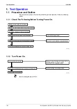
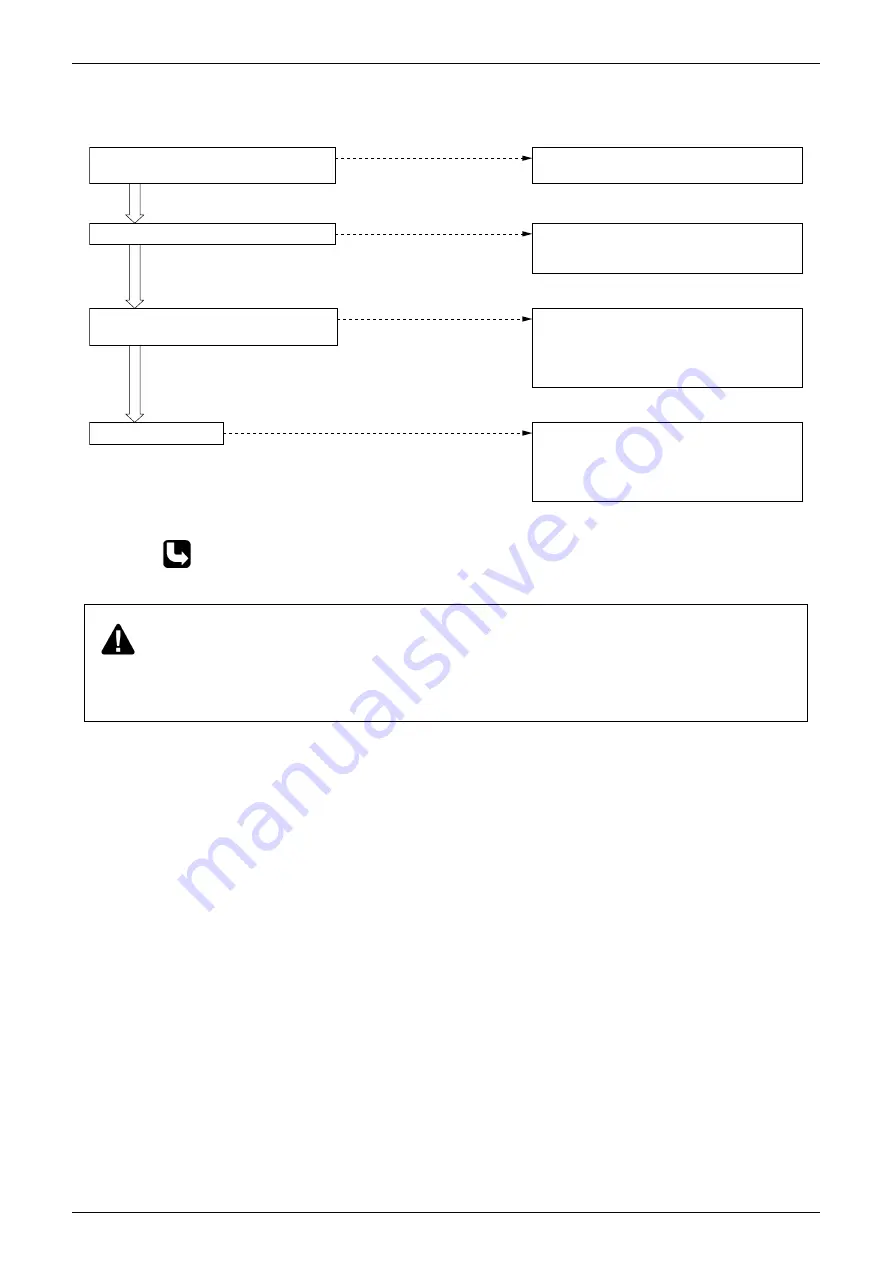
1.1.3 Check Operation.
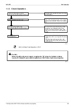
Refer to Wiring Check Operation on P121
Carry out wiring check operation,
and check wiring and piping connections.
Set the operation mode to ”cool.“
Set to the test operation mode
and operate using the remote controller.
Normal operation
For wiring check operation procedure, see wiring
check operation.
Even if it's the heating season, set to cooling
mode in order to prevent liquid from backing
up.
To enter the test operation mode, push the
inspection / test operation button of the
indoor unit remote controller 4 times. Push
once more to return to the normal operation
mode.
•Make sure cold air is coming from the indoor
unit.
•Run the indoor units one at a time, and
make sure that the corresponding outdoor
units also run.
(VF130)
Caution
When the 400 volt power supply is applyed to "N" phase by mistake, replace
Inverter P.C.B (A2P) and control transformer (T1R, T2R) in switch box together.
(V0847)
Содержание R407C PLUS
Страница 1: ...System R407C PLUS Series Heat Recovery System Si33 105 Service Manual ...
Страница 11: ...Introduction Si33 105 x ...
Страница 41: ...Specifications Si33 105 30 Specifications R407C PLUS Series Heat Recovery System ...
Страница 147: ...Test Operation Si33 105 136 Test Operation R407C PLUS Series Heat Recovery System ...
Страница 158: ...Si33 105 Troubleshooting by Remote Controller Troubleshooting R407C PLUS Series Heat Recovery System 147 ...
Страница 160: ...Si33 105 Troubleshooting by Remote Controller Troubleshooting R407C PLUS Series Heat Recovery System 149 ...
Страница 229: ...Troubleshooting OP Unified ON OFF Controller Si33 105 218 Troubleshooting R407C PLUS Series Heat Recovery System ...
Страница 232: ...Si33 105 Piping Diagram Appendix R407C PLUS Series Heat Recovery System 221 RSEYP24 26 28 30KJY1 3D031938 ...
Страница 234: ...Si33 105 Piping Diagram Appendix R407C PLUS Series Heat Recovery System 223 BSVP250KJV1 4D014499A ...
Страница 237: ...Wiring Diagram Si33 105 226 Appendix R407C PLUS Series Heat Recovery System RSEYP24 26 28 30KJY1 3D031467 ...
Страница 238: ...Si33 105 Wiring Diagram Appendix R407C PLUS Series Heat Recovery System 227 2 2 BS Unit 3D014829B ...
Страница 240: ...Si33 105 Wiring Diagram Appendix R407C PLUS Series Heat Recovery System 229 FXYFP32 40 50 63 80 100 125KVE 3D020238B ...
Страница 241: ...Wiring Diagram Si33 105 230 Appendix R407C PLUS Series Heat Recovery System FXYCP20 25 32 63KV1 DU229 5139C ...
Страница 242: ...Si33 105 Wiring Diagram Appendix R407C PLUS Series Heat Recovery System 231 FXYCP40 50 80 125KV1 DU230 522C ...
Страница 243: ...Wiring Diagram Si33 105 232 Appendix R407C PLUS Series Heat Recovery System FXYKP25 32 40 63KV1 DU227 544C ...
Страница 244: ...Si33 105 Wiring Diagram Appendix R407C PLUS Series Heat Recovery System 233 FXYSP20 25 32 40 50 63KV1 DU227 545E ...
Страница 245: ...Wiring Diagram Si33 105 234 Appendix R407C PLUS Series Heat Recovery System FXYSP80 100 125KV1 DU230 519D ...
Страница 246: ...Si33 105 Wiring Diagram Appendix R407C PLUS Series Heat Recovery System 235 FXYMP40 50 63 80 100 125KV1 DU229 5140C ...
Страница 247: ...Wiring Diagram Si33 105 236 Appendix R407C PLUS Series Heat Recovery System FXYMP200 250KV1 3D011012B ...
Страница 248: ...Si33 105 Wiring Diagram Appendix R407C PLUS Series Heat Recovery System 237 FXYHP32 63 100KV1 DU228 531C ...
Страница 249: ...Wiring Diagram Si33 105 238 Appendix R407C PLUS Series Heat Recovery System FXYAP20 25 32 40 50 63KV1 DU221 561F ...
Страница 263: ...Si33 105 iv Index ...


