background image

IOM 1264-1 (09/18) 

©2018 Daikin Applied   |   (800) 432–1342   |   www.DaikinApplied.com

Daikin Applied Training and Development

Now that you have made an investment in modern, efficient Daikin Applied equipment, its care should 

be a high priority. For training information on all Daikin Applied HVAC products, please visit us at 

www.DaikinApplied.com and click on Training, or call 540-248-9646 and ask for the Training Department.

Warranty

All Daikin Applied equipment is sold pursuant to its standard terms and conditions of sale, including 

Limited Product Warranty. Consult your local Daikin Applied representative for warranty details. To find 

your local Daikin Applied representative, go to www.DaikinApplied.com.

Aftermarket Services

To  find  your  local  parts  office,  visit  www.DaikinApplied.com  or  call  800-37PARTS  (800-377-2787). 


To find your local service office, visit www.DaikinApplied.com or call 800-432-1342.

This document contains the most current product information as of this printing. For the most up-to-date 

product information, please go to www.DaikinApplied.com.

Products manufactured in an ISO Certified Facility.

Содержание Navigator WWV

Страница 1: ...on Operation and Maintenance Manual Navigator Water cooled Screw Chillers Model WWV 120 to 300 Tons 527 to 1055 kW HFC 134a Refrigerant 50 60 Hz IOM 1264 1 Group Chiller Part Number IOM1264 1 Date September 2018 ...

Страница 2: ...oduct at the time of publication and we reserve the right to make changes in design and construction at any time without notice Introduction 5 Installation and Application Considerations 7 Installation Knockdown 15 Dimensional Drawings 19 Controller Operation 20 Unit Functions 25 Circuit Functions 31 Alarms and Events 35 Using the Controller 45 Startup and Shutdown 46 System Maintenance 47 Table o...

Страница 3: ...Transducers installed and wired properly Wiring complies with National Electrical Code and local codes see notes Remote EXV wired with shielded cable if applicable Miscellaneous Yes No N A Initials Unit control switches all off Remote Evaporator Piping factory reviewed and approved if applicable All refrigerant components piping leak tested evacuated and charged Thermometers wells gauges control e...

Страница 4: ......

Страница 5: ...ds when halo carbon refrigerant travels in a rubber hose A grounding strap must be used between the auxiliary refrigerant tank and the chiller s end sheet earth ground which will safely take the charge to the ground Damage to sensitive electronic components could occur if this procedure is not followed CAUTION This equipment generates uses and can radiate radio frequency energy If not installed an...

Страница 6: ...r in identifying alarm and fault causes Only normal field connections such as water piping electric power and control interlocks are required thereby simplifying installation and increasing reliability Necessary equipment protection and operating controls are included All Daikin Applied screw chillers must be commissioned by a Daikin Applied service technician or an authorized service provider Fai...

Страница 7: ...potential injury hazard Avoid contact with them WARNING Escaping refrigerant can displace air and cause suffocation Immediately evacuate and ventilate the equipment area If the unit is damaged follow Environmental Protection Agency EPA requirements Do not expose sparks arcing equipment open flame or other ignition source to the refrigerant DANGER Improper rigging lifting or moving of a unit can re...

Страница 8: ...alve Thus safety valves must be connected outside of the equipment room Mounting Hole Access After positioning the shipping rails should be removed and the machine must be firmly anchored to the ground or foreseen metal structure to support the machine In this regard 0 87 in 22 mm diameter holes are included on the unit supports for securing mounting bolts etc Mounting location dimensions are give...

Страница 9: ...tor cannot exceed 110 F Water this hot can damage controls or cause the relief valve to discharge refrigerant Piping must be supported to eliminate weight and strain on the fittings and connections Chilled water piping must be adequately insulated System Water Volume All chilled water systems need adequate time to recognize a load change respond to that load change and stabilize without undesirabl...

Страница 10: ...d it will be reduced to a flow of 140 gpm the change in flow is 60 gpm Ten percent of 200 gpm equals 20 gpm change per minute or a minimum of three minutes to go from maximum to desired flow Glycol Solutions Test coolant with a clean accurate glycol solution hydrometer or refractometer to determine the freezing point On glycol applications the supplier normally recommends that a minimum of 25 solu...

Страница 11: ...nit controller can send a 0 10Vdc signal to the valve to modulate its position Figure 4 Water Tower Connections 2 Way Valve Three Way Bypass Valve Operation To modulate the water temperature in the condenser install a three way by pass valve Figure 5 shows how the three way valve is applied in the condenser water system The three way valve position can be modulated by a 0 10Vdc signal from the uni...

Страница 12: ...be installed in accordance with the required version of NECA AA 104 Standard for Installing Aluminum Building Wire and Cable ANSI All wiring within the unit is sized in accordance with the U S A National Electrical Code Refer to the unit nameplate and the unit selection report for the correct electrical ratings DANGER Qualified licensed electricians must perform wiring Electrical shock hazard exis...

Страница 13: ...pply power from the generator back to the utility power grid Transferring power while the chiller is running can cause severe chiller damage The necessary procedure for reconnecting power from the generator back to the utility grid is as follows 1 Set the generator to always run five minutes longer than the unit start to start timer which can be set from two to sixty minutes while keeping the chil...

Страница 14: ...o 1 BY OTHERS BY OTHERS COOLING TOWER RELAY 120VAC 0 25AMP MAX MODE SWITCH M5 M5 1 2 3 5 4 17 7 8 11 12 13 14 15 16 17 25 24 CONTACTS RATED FOR 24 VOLTS AC AND 8mA DO NOT APPLY VOLTAGE FROM EXTERNAL SOURCE IF REMOTE SWITCH IS USED REMOVE MECHANICAL JUMPER BETWEEN M5 TERMINALS 24 25 TO FROM BAS CUSTOMER CONNECTION CLA CLB CONNECT TO GROUND AT ONE END ONLY TO FROM BAS CUSTOMER CONNECTION REF CONNECT...

Страница 15: ...plates are required to cover any refrigerant connection left open for extended periods of time Contact Daikin Applied service to obtain these parts Ideal for retrofit applications where site diassembly is needed due to installation clearances Figure 11 Knockdown Piping Connections Exploded View Type B Knockdown Bolted Construction Shipped as Parts Compressor s power boxes and control box are remov...

Страница 16: ... 27 1 28 0 1534 MNNS 61 6 28 0 29 1 1925 RNNS 64 6 30 5 31 4 2778 Combined Unit Configurations E16 C18 E16 C20 E20 C20 E24 C24 Length in 150 7 149 7 149 8 152 Width in 23 2 23 2 25 2 30 4 Height in 61 2 61 2 65 4 73 3 Separated Evaporator Separated Condenser E16 E20 E24 C18 C20 C24 Length in 143 2 144 3 142 7 150 7 149 3 151 5 Width in 23 2 25 2 30 4 21 3 23 7 28 4 Height in 31 7 35 9 38 5 33 8 34...

Страница 17: ...ess assemblies from the bottom of the VFD to the unit control box and to compressor terminal box but leave the bus bars electrical barrier ground strap and fittings installed Figure 14 Power Wiring Inside VFD 7 Disconnect the thermister wires from the compressor terminal box and coil them inside the VFD do not disconnect from the VFD terminal block Unbolt VFD from mounting brackets and use lifting...

Страница 18: ...e careful to avoid damaging lines already mounted on the unit Mounting bolts washers and nuts are shipped loose Leave the mounting bolts loose until the suction and discharge lines are installed and aligned During assembly bolts holding block off plates are used for reassembly of the component 3 Do not remove block offs until ready to install piping The compressor and vessels have a Schrader valve...

Страница 19: ...Operating Weight lbs J E1610 KB C1810 KB 150 7 162 2 55 1 84 3 5007 6877 J E1610 JB C1810 JB 150 7 162 2 55 1 84 3 5166 6954 J E1610 HB C2010 JB 149 3 163 8 55 1 84 3 5811 7762 M E1610 HB C1810 HB 150 7 162 2 55 1 85 3 5457 7196 M E1610 HB C2010 JB 149 3 163 8 55 1 85 3 5894 7845 M E1610 GB C2010 JB 149 3 163 8 55 1 85 3 6105 8026 M E2010 HB C2010 HB 149 3 163 8 57 1 89 7 6589 8918 M E2010 GB C201...

Страница 20: ...ignal Off Signal On DI1 Unit Ground Fault Relay Fault No Fault DI2 Evaporator Flow Switch No Flow Flow DI4 Remote Switch Unit disable Unit enable DI5 Unit Switch Unit disable Unit enable DI6 External Alarm Unit disable Unit enable X1 Emergency Stop Unit off Unit enable X2 Mode Switch Cool Mode Ice Mode X8 Condenser Flow Switch No Flow Flow Table 12 Digital Outputs Description Output OFF Output ON ...

Страница 21: ...able Enable Control source Local Local Network Available Modes only changeable when Unit Switch is off Cool Cool Cool w Glycol Cool Ice w Glycol Ice w Glycol Test Staging and Capacity Control Cool LWT 44 6 F 7 C See below Ice LWT 24 8 F 4 C 7 6 to 39 2 F 8 to 4 C Start Up Delta T 4 9 F 2 7 C 3 to 9 F 1 66 to 5 C Shut Down Delta T 2 7 F 1 5 C 1 8 to 3 6 F 1 to 2 C Ice Cycle Delay 12 1 23 hours Clea...

Страница 22: ...nser Offset 0 F 0 C 9 0 to 9 0 F 5 0 to 5 0 C Evaporator EWT Senser Offset 0 F 0 C 9 0 to 9 0 F 5 0 to 5 0 C Condenser LWT Senser Offset 0 F 0 C 9 0 to 9 0 F 5 0 to 5 0 C Condenser EWT Senser Offset 0 F 0 C 9 0 to 9 0 F 5 0 to 5 0 C Circuit Configuration Pumpdown Pressure 200 0 kPa 29 0 psi 70 to 280 kPa 10 2 to 40 6 psi Pumpdown Time Limit 120 sec 0 to 180 sec Start To Start Time Delay 15 min 15 ...

Страница 23: ...t mode is no longer Test all unit test mode set points will be changed back to the off values Table 20 Administration and Service Support Description Default Range Unit G O Number Enter Data Alphanumeric string of up to 16 characters Unit Serial Number Enter Data Alphanumeric string of up to 20 characters Next Maintenance Month January January through December Next Maintenance Year 2017 2009 2200 ...

Страница 24: ...inimum speed calculated for automatic control The maximum value is equal to the Compressor Maximum Speed setting The Manual VR setting value will follow the target capacity while VR Control Auto When VR Control is set to Manual the Manual VR set point can be set to the desired value Sensor Offsets Evaporator Pressure Offset 0 psi 0 kPa 14 5 to 14 5 psi 100 to 100 kPa Condenser Pressure Offset 0 ps...

Страница 25: ...e from The Available Modes Set Point must only be changed when the unit switch is off This is to avoid changing modes of operation inadvertently while the chiller is running Unit Mode is set according to the following table Table 26 Unit Mode Combinations Available Modes Set Point Control Source Set Point Mode Input BAS Request Unit Mode Cool Cool Cool w Glycol Cool Cool Ice w Glycol Local Off Coo...

Страница 26: ...TO Wait Cond Flow or Wait Evap Flow Unit State Auto Evaporator State Start and Flow Switch input is off or Condenser State Start and Flow Switch input is off 12 AUTO Pumpdown Unit State Pumpdown 13 AUTO Max Pulldn Rate Unit State Auto unit capacity limited by the evap EWT pulldown rate 14 AUTO Unit Cap Limit Unit State Auto unit capacity limit has been met or exceeded 15 OFF Cfg Chg Rst Ctrl A con...

Страница 27: ...rator Flow Loss Delay set point value the primary pump will shut off and the standby pump will start Once the standby pump is started the flow loss alarm logic will apply if flow cannot be established in the evaporator start state or if flow is lost in the evaporator Run state Auto Control If auto pump control is selected the primary standby logic above is still used When the evaporator is not in ...

Страница 28: ...ge or Valve SP VFD Stage The second fan stage should turn off when the following conditions are met Stage timer Tower Fan Stage Off Delay set point CP Stage 2 On Temperature set point Stage Off Differential set point Bypass valve position Stage Off Position Speed set point if Valve VFD Control Configuration Valve Stage VFD Speed Stage Off Position Speed set point if Valve VFD Control Configuration...

Страница 29: ...er Fan Stage 2 On Temperature As the calculated speed varies from 0 to 100 the voltage signal for the Tower VFD Speed output should vary from 0 to 10 VDC Leaving Water Temp LWT Target The LWT Target varies based on settings and inputs The base LWT Target is selected as shown inTable 28 Table 28 LWT Targets Control Source Available Modes Set Point Control Source Set Point Mode Input BAS Request Bas...

Страница 30: ...unit control source is set to network The signal will be received through the BAS interface on the unit controller This network limit command directly sets a max unit capacity from 0 to 100 RapidRestore Option RapidRestore is an option that can be added to WWV chillers The general purpose of the option is to allow the capability to restart more quickly and to load faster than normal when power is ...

Страница 31: ...e Pumpdown set point Disable Then Pumpdown Target Evaporator Pressure at pumpdown start 20 kPa with value limited to the range from 35 kPa to the maximum Pumpdown Pressure set point If Service Pumpdown set point Enable Then Pumpdown Target 35 kPa Circuit Availability A circuit is available to start if the following conditions are true No manual reset circuit fault alarms are active Circuit Mode se...

Страница 32: ... more than one status is enabled at the same time the highest numbered status overrides the others and is displayed Table 29 Circuit Status Status Conditions 0 Off Ready Circuit is ready to start when needed 1 Off Cycle Timer Circuit is off and cannot start due to active cycle timer 2 Off Max Starts Per Hour Circuit is off and cannot start due to compressor reaching max starts per hour 3 Off BAS D...

Страница 33: ...ds changes to the speed are performed based on load and unload commands coming from the unit capacity control logic The speed is constrained to a range from the minimum based on the configuration up to the Compressor Maximum Speed set point When a capacity increase occurs a time delay starts and when a capacity decrease occurs a separate time delay starts While either of these delays is active no ...

Страница 34: ...refrigerant level at an optimal level Oil Return Solenoid Valve The oil return solenoid valve output should be on whenever the compressor is being commanded to run This output activates the oil return solenoid valve as well as the jet pump solenoid valve Circuit Capacity Overrides The following conditions override automatic capacity control as described These overrides keep the circuit from enteri...

Страница 35: ... An alarm bell icon will be displayed in the upper right hand corner of all controller screens including the optional remote user interface panel s screens An optional field supplied and wired remote alarm device will be activated Clearing Alarms Faults Active alarms can be cleared through the unit controller HMI display or a BAS network Alarms are automatically cleared when controller power is cy...

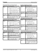
Страница 36: ...oss alarm is cleared If active via trigger condition 2 If the flow loss alarm has occurred due to this trigger it is always a manual reset alarm Condenser Flow Loss Displayed Text Cond Water Flow Loss Trigger 1 Condenser Pump State Run AND Condenser Flow Digital Input No Flow for time Flow Loss Delay set point AND at least one circuit is not in the Off state 2 Condenser Pump State Start for time g...

Страница 37: ...alarm can be cleared manually via the unit controller HMI or BAS command if the following are true Resistance value is from 340 Ω to 300k Ω Reliability value reported for input is NoFault Evaporator Condenser EWT Sensor Fault Displayed Text Evap EWT SenFault Cond EWT SenFault Trigger If any of the following occur Resistance value is 340 Ω Resistance value is 300k Ω Reliability value reported for i...

Страница 38: ...en Demand Limit set point is set to Disable or demand limit input back in range for 5 seconds Bad LWT Reset Input Displayed Text Bad LWT Reset Input Trigger LWT Reset set point is Enable and LWT reset input is out of range For this alarm out of range is considered to be a signal less than 3mA or more than 21mA Action Taken LWT reset signal and reset function are ignored Reset Auto clear when LWT R...

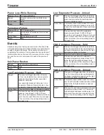
Страница 39: ...on Taken Normal shutdown of unit and lock out from running Reset This alarm can be cleared manually via the Unit Controller HMI or via BAS command High Oil Pressure Difference Displayed Text C1 Oil PD High Trigger Circuit is in the Run state and Oil Pressure Difference High Oil Pressure Difference value for a time longer than High Oil Pressure Difference Delay set point High Oil Pressure Differenc...

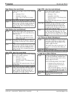
Страница 40: ...hours Prior occurrences are events Action Taken Rapid shutdown of unit and lock out from running on the third occurrence Reset This alarm will auto clear on the first and second occurrences This third occurrence can be cleared manually via the Unit Controller HMI or via BAS command High Motor Current Displayed Text C1 MotorCurrent High Trigger If all of the following are true the alarm is triggere...

Страница 41: ...of unit and lock out from running Reset This alarm will automatically reset when none of the motor phase loss alarm flags are set for at least five seconds Mains Phase Loss Displayed Text C1 CmpVfd Phase Loss Trigger Compressor VFD sets the Mains Phase Loss alarm flag for at least one second or the Mains Failure warning flag for at least 2 5 seconds Action Taken Rapid shutdown of unit and lock out...

Страница 42: ...r input voltage is 400mv to 4600mv for at least five seconds Suction Temp Sensor Fault Displayed Text C1 SuctTempSenFault Trigger Trigger if UC communication with EEXV1 module is OK and any of the following are true for at least one second Sensor input value 340 Ω Sensor input value 300 kΩ Sensor reliability reported by control system No Fault Action Taken Rapid shutdown of unit and lock out from ...

Страница 43: ...Pressure Unload Trigger This event will trigger when the unit mode is Cool the circuit state is Run and evaporator pressure drops below the Low Evaporator Pressure Unload set point Action Taken Compressor speed will decrease 1Hz every second until evaporator pressure rises up to at least the Low Evaporator Pressure Unload set point Reset This event is reset when the evaporator pressure rises at le...

Страница 44: ...inutes It is also reset when the compressor is no longer running or the unit operating mode is changed to Ice High VFD Line Current Unload Trigger This event will trigger when all of the following are true for at least 5 seconds Unit mode Cool compressor is running VFD Line Current VFD Primary RLA set point x 1 05 VFD Primary RLA set point is part of the unit configuration Action Taken Compressor ...

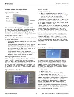
Страница 45: ...e set point The first line visible on each display includes the menu title and the line number indicating which menu number you are on and the total number of menus In the above menu screen the title is Cir 1 Data and it is menu 1 of 22 The right most position of the title line includes an up arrow to indicate there are menus parameters above the currently displayed line and or a down arrow to ind...

Страница 46: ... After the compressors have pumped down turn off the chilled water pump CAUTION Water flow to the unit must not be interrupted before the compressors pump down to avoid freeze up in the evaporator Interruption will cause equipment damage Startup After Temporary Shutdown 1 Start the chilled water pump 2 With System switch Q0 in the on position move pumpdown switches Q1 and Q2 to the auto position 3...

Страница 47: ...cation POE type oil is used for compressor lubrication This type of oil is extremely hygroscopic which means it will quickly absorb moisture if exposed to air and form acids that can be harmful to the chiller Avoid prolonged exposure of refrigerant to the atmosphere to prevent this problem CAUTION POE oil must be handled carefully using proper protective equipment gloves eye protection etc The oil...

Страница 48: ...from joint faces Inspect parts individually for damage and ensure they are completely clean before laying them out on a clean surface in a logical order ready for reassembly Use fresh refrigerant oil to lubricate parts during reassembly 1 Install new O rings on the oil filter housing cover 2 Insert new oil filter into the housing ensuring the filter sits tightly on the sealing spigot 3 Replace the...

Страница 49: ...e chiller control senses the chilled water temperature It also signals the chilled water pump to start to providing flow through the evaporator and additional protection against evaporator and outside pipe freeze up Other pump starting methods will not automatically provide this protection Note the owner operator must be aware that when the water temperature falls below freezing temperatures it is...

Страница 50: ...ating X Megger compressor motor X Refrigeration Lubricant Leak test X Check liquid line sight glasses for clear flow X Check oil sight glass for correct level lubricant charge X Perform compressor vibration test optional X Perform oil analysis test on compressor oil X Evaporator and Condenser water cooled Confirm correct water flow and pressure drop X Confirm appropriate water treatment X Clean an...

Страница 51: ...h above such free labor does not include diagnostic visits inspections travel time and related expenses or unusual access time or costs required by product location 2 Refrigerants fluids oils and expendable items such as filters are not covered by this warranty 3 This warranty shall not apply to products or parts which a have been opened disassembled repaired or altered by anyone other than Compan...

Страница 52: ...is sold pursuant to its standard terms and conditions of sale including Limited Product Warranty Consult your local Daikin Applied representative for warranty details To find your local Daikin Applied representative go to www DaikinApplied com Aftermarket Services To find your local parts office visit www DaikinApplied com or call 800 37PARTS 800 377 2787 To find your local service office visit ww...

Отзывы: