


D-EIMWC00908-16EN - 26/52
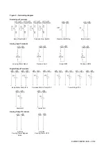
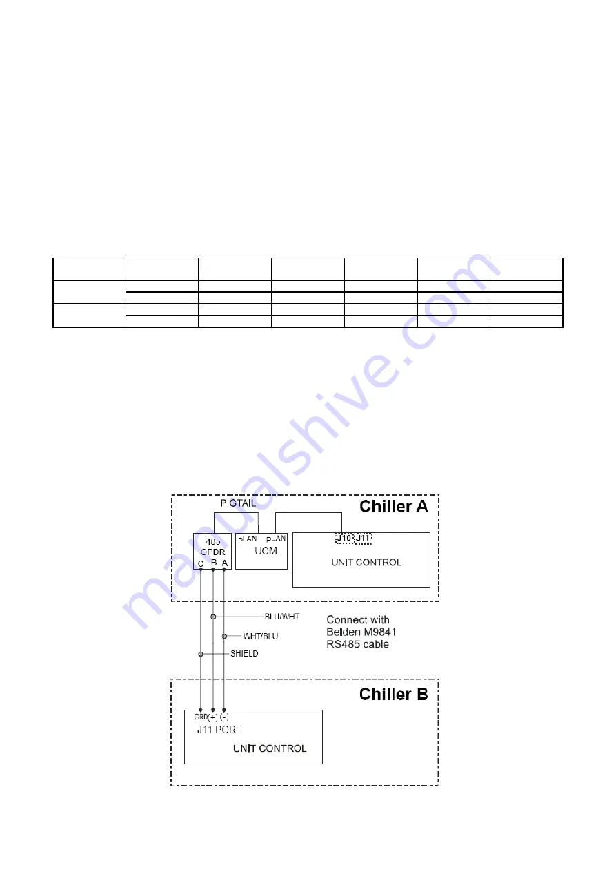
4. Connect chillers together (RS485 wiring) as shown in Figure 7. The first chiller in the connection can be designated
as Chiller A. The isolation board is attached to the DIN rail adjacent to the Chiller A unit controller. The isolation board
has a pigtail that is plugged into J10 on the controller. Most chillers will already have a universal communication
module (UCM) that connects the controller to the touchscreen already plugged onto J10. If this is the case, plug the
isolation module pigtail into the empty RJ11 pLAN port on the UCM. This is equivalent to plugging into the unit
controller directly.
Next, interconnecting wiring is needed between Chiller A and Chiller B.
Interconnection
: Belden M9841 (RS 485 Spec Cable) is wired from the 485OPDR isolation board (terminals A, B,
and C) on Chiller A to the J11 port on the unit controller of Chiller B. At J11, the shield connects to GND, the
blue/white wire to the (+) connection, and the white/blue to the (-) connection.
Note that Chiller B does not have, or need, an isolation board.
5. Verify correct nodes on each OITS Service Screen.
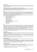
Table 4 - Electrical data
Chiller
(1)
Comp 1
Controller
Comp 2
Controller
Unit
Controller
Reserved
Operator
Interface (2)
Reserved
A
1
2
5
6
7
8
100000
010000
101000
011000
111000
000100
B
9
10
13
14
15
16
100100
010100
101100
011100
111100
000010
Notes:
6.
Up to four single or dual compressors can be interconnected.
7.
The Operator Interface Touch Screen (OITS) setting is not a DIP switch setting. The OITS address is selected by
selecting the ‘service’ set screen. Then, with the Technician level password active, select the ‘pLAN Comm’
button. Buttons A(7), B(15), C(23), D(31) will appear in the middle of the screen, then select the letter for the OITS
address for the chiller that it is on. Then close the screen. Note that A is the default setting from the factory.
8.
Six Binary Switches: Up is ‘On’, indicated by ‘1’. Down is ‘Off’, indicated by ‘0’
.
Figure 7
– Field wiring diagram
Содержание EWWD320
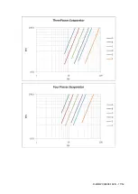
Страница 16: ...D EIMWC00908 16EN 16 52 Figure 4 Evaporator pressure drop...
Страница 17: ...D EIMWC00908 16EN 17 52...
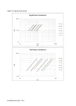
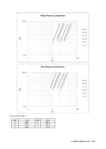
Страница 18: ...D EIMWC00908 16EN 18 52 Figure 5 Condenser pressure drop...
Страница 31: ...D EIMWC00908 16EN 31 52 Figure 9 Refrigeration cycle a Single compressor unit b Dual compressor unit...
Страница 34: ...D EIMWC00908 16EN 34 52 Figure 12 Compressor overview...
Страница 50: ...D EIMWC00908 16EN 50 52...
Страница 51: ...D EIMWC00908 16EN 51 52...