


Operation manual
9
EWAQ+EWYQ009~0 EWAQ+EWYQ009~013ACW1
Packaged air-cooled water chillers and packaged reversible air to
water heatpumps
4PW51588-1
O
PERATING
THE
REMOTE
ALARM
OPTION
The optional EKRP1HB remote alarm address card can be used to
remotely monitor your system. This address card offers 2 voltage free
outputs.
■
Output 1 = alarm output: this output will be enabled when your
unit is in error condition in case of default setting of field setting
parameter [C-01]. Refer to
"[C] Alarm output logic of EKRP1HB"
for other possibilities.
■
Output 2 = ON/OFF output: this output will be enabled when
your unit is in ON condition.
For more details about the wiring connections of this option, refer to
the wiring diagram of the unit.
F
IELD
SETTINGS
The unit should be configured by the installer to match the installation
environment (outdoor climate, installed options, etc.) and user
demand. Thereto, a number of so called field settings are available.
These field settings are accessible and programmable through the
user interface.
Each field setting is assigned a 3-digit number or code, for example
[5-03], which is indicated on the user interface display. The first digit
[5] indicates the 'first code' or field setting group. The second and
third digit [03] together indicate the 'second code'.
A list of all field settings and default values is given under
. In this same list, we provided for 2
columns to register the date and value of altered field settings at
variance with the default value.
A detailed description of each field setting is given under
Procedure
To change one or more field settings, proceed as follows.
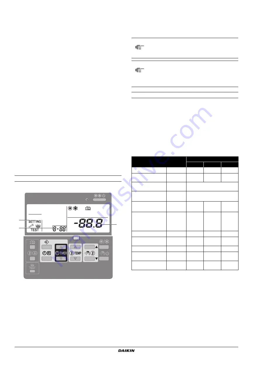
1
Press the
z
button for a minimum of 5 seconds to enter FIELD
SET MODE.
The
$
icon (3) will be displayed. The current selected field
setting code is indicated
;
(2), with the set value displayed to
the right
-
(1).
2
Press the
bgi
button to select the appropriate field
setting first code.
3
Press the
bgj
button to select the appropriate field
setting second code.
4
Press the
pfi
button and
pfj
button to change
the set value of the select field setting.
5
Save the new value by pressing the
pr
button.
6
Repeat step 2 through 4 to change other field settings as
required.
7
When finished, press the
z
button to exit FIELD SET MODE.
Detailed description
[0] User permission level
If required, certain user interface buttons can be made unavailable for
the user.
Three permission levels are defined (see the table below). Switching
between level 1 and level 2/3 is done by simultaneously pressing
buttons
pfi
and
pfj
immediately followed by
simultaneously pressing buttons
s
and
ba
, and keeping all 4
buttons pressed for at least 5 seconds (in normal mode). Note that no
indication on the user interface is given. When level 2/3 is selected,
the actual permission level — either level 2 or level 3 — is
determined by the field setting [0-00].
2
3
1
NOTE
Changes made to a specific field setting are only
stored when the
pr
button is pressed. Navigating to a
new field setting code or pressing the
z
button will
discard the change made.
NOTE
■
Before shipping, the set values have been set as
shown under
"Field settings table" on page 12
■
When exiting FIELD SET MODE, "
88
" may be
displayed on the user interface LCD while the unit
initialises itself.
Button
Permission level
1
2
3
On/off button
o
operable
operable
operable
Operation changeover
button
h
/
c
operable
operable
operable
Sanitary water heating
button
w
– Not available –
Sanitary temperature
adjust buttons
wbi
wbj
– Not available –
Temperature adjust
buttons
bgi
bgj
operable
operable
operable
Time adjust buttons
pf
i
pf
j
operable
Programming button
<
operable
Schedule timer enable/
disable button
pr
operable
operable
Quiet mode button
s
operable
Weather dependent
set point button
ba
operable
Inspection/test
operation button
z
operable
Содержание EWAQ009ACV3
Страница 15: ......
Страница 16: ...4PW51588 1 Copyright Daikin ...