background image

Operation manual

7

EWAD120~340MBYNN

Packaged air-cooled water chillers

4PW22683-1

Switching the unit on

1

Press the 

J

 key on the controller.

Depending on wheter or not a remote ON/OFF switch has been
configured (

refer to the installation manual

), the following

conditions may occur.
When no remote ON/OFF switch is configured, the LED inside
the 

J

 key lights up and an initialization cycle is started. Once all

the timers have reached zero, the unit starts up.
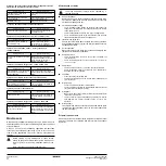
When a remote ON/OFF switch is configured, the following table
applies:

2

If the water chiller does not start after a few minutes, refer to

"Troubleshooting" on page 15

.

Switching the unit off

If no remote on/off switch is configured:

Press the 

o

 key on the controller.

The LED inside the 

o

 key goes out.

If a remote on/off switch is configured:

Press the 

o

 key on the controller or switch the unit off using the

remote on/off switch.
The LED inside the 

o

 key goes out in the first case and starts

blinking in the second case.

Switching units ON/OFF in a DICN system

If the 

o

 key is pressed on a unit with status 


 or 

, all

other units with status 


 or 

 will be ON or OFF.

If the 

o

 key is pressed on a unit with status 


,

only this unit will be ON or OFF.

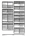
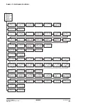
Consulting actual operational information

1

Enter the readout menu. Refer to the chapter 

"How to enter a

menu" on page 6

.

The controller automatically shows the first screen of the
readout menu which provides the following information:


  or 

  or 

:  manual/

automatic control mode operation. If the automatic control mode
is selected, the controller will indicate the active temperature
setpoint. Depending on the status of the remote contact, setpoint
one or setpoint two is active.


: actual evaporator inlet water temperature.


: actual evaporator outlet water temperature.

2

Press the 

h

 key to enter the next screen of the readout menu.

The 


  screen of the readout menu provides

information concerning the status of the different circuits.

: actual status of circuit 1.

: actual status of circuit 2.

When the circuit is ON, the following status information may
appear.

: 40% - this percentage refers to the activated capacity of that

specific circuit.

When a circuit is OFF, the following status information may
appear.


:  one of the circuit safety devices is activated

(refer to 

"Troubleshooting" on page 15

).


: the circuit is limited by a remote contact.


: the actual value of one of the software timers is

not zero (refer to 

"Timers menu" on page 9

).


 the circuit is ready to start up when extra cooling

load is needed.

The preceding OFF messages are written down in order of priority. If
one of the timers is busy and one of the safeties is active, the status
information says 


.

The 


  is written down on the bottom of the screen.

The percentage is the actual cooling capacity of the unit.

3

Press the 

h

 key to enter the next screen of the readout menu.

The 


 screen of the readout menu provides

information concerning the pressures of circuit.

/

: high pressure of the refrigerant in circuit 1/2. The first

number stands for the pressure in bar, the second number
stands for the bubble point saturation temperature in degrees
Celsius.

/

:  low pressure of the refrigerant in circuit 1/2. The first

number stands for the pressure in bar, the second number
stands for the dew point saturation temperature in degrees
Celsius.

4

Press the 

h

 key to enter the next screen of the readout menu.

To  consult actual operational information about the ambient
temperature and the total running hours of the compressor.

5

Press the 

g

 key to return to the other readout menus.

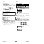
Local key

Remote switch

Unit

o

o

o

o

 LED

ON

ON

ON

ON

ON

OFF

OFF

Flashing

OFF

ON

OFF

OFF

OFF

OFF

OFF

OFF

In case of emergency, switch off the unit by pushing the
emergency stopbutton.

NOTE

Also consult 

"Defining the schedule timer" on page 12

and “Customization in the service menu” chapter
“Setting of the changeable inputs and outputs” in the
installation manual.

NOTE

When a remote ON/OFF switch is configured, the
remote ON/OFF contact for all units with status


 or 

 of a DICN network is the contact

connected to the master unit.

For units with status 


, the remote

contact is the contact connected to this unit.

NOTE

If the user wants 1 unit to operate on his command
only, this unit is to be set to 


.

It is recommended not to select the master unit for this
purpose. Even if the status of the master is set to


, it will still be the contact

connected to the master which will switch ON/OFF the
other units in 


  or 

  mode. It would

therefore never be possible to only switch the master
unit OFF remotely.

Switching OFF the master unit only, should in this case
be done by the local ON/OFF key on the master unit.

NOTE

For a DICN system, the 


 values are the values of the individual units, not

of the system. Temperatures of the system can be
consulted in the first screen of the network menu.

NOTE

When a circuit in is in a high pressure setback, the
indication of capacity will be flashing. A high pressure
setback is a prevention of load-up or a forced load-
down caused by a too high pressure.

Содержание EWAD120MBYNN1

Страница 1: ...OPERATION MANUAL EWAD120MBYNN1 EWAD150MBYNN1 EWAD170MBYNN1 EWAD240MBYNN1 EWAD300MBYNN1 EWAD340MBYNN1 Packaged air cooled water chillers...

Страница 2: ...e that it has been properly installed It is therefore necessary to carefully read the installation manual supplied with the unit and the recommendations listed in Checks before initial start up on pag...

Страница 3: ...rge evaporator 19 Field wiring intake 2 Condenser 11 Leaving water temperature sensor R4T 20 Main isolator switch optional S13S 3 Compressor 1 M1C 12 Entering water temperature sensor R3T 21 Compresso...

Страница 4: ...the evaporator of the unit against freezing when there is no waterflow or when the waterflow is too low Safety devices The unit is equipped with three kinds of safety device 1 General safety devices...

Страница 5: ...ntroller A11P Expansion board controller only for EWAD240 340 B1P B4P Low pressure transmitter for circuit 1 circuit 2 B2P B5P High pressure transmitter for circuit 1 circuit 2 C1 C3 Capacitor E1HC E2...

Страница 6: ...ted by paper sheets cardboard or any other material 12 Power supply voltage Check the power supply voltage on the local supply panel The voltage should correspond to the voltage on the identification...

Страница 7: ...with the everyday usage of the unit Here you will find how to perform routine tasks such as Setting the language on page 6 Switching the unit on on page 7 Consulting actual operational information on...

Страница 8: ...rs menu on page 9 the circuit is ready to start up when extra cooling load is needed The preceding OFF messages are written down in order of priority If one of the timers is busy and one of the safeti...

Страница 9: ...ll function as stand alone units If a slave unit can not be found by the network the red light inside the p key of the master lights up and the buzzer inside the control is activated If the master can...

Страница 10: ...atus To consult information about the pressures of circuit 1 To consult information about the pressures of circuit 2 only for EWAD240 340 To consult actual operational informa tion about the ambient t...

Страница 11: ...f the compressors at the moment of shutdown To check which were the pressures of the circuit 1 at the moment of shutdown To check which were the pressures of the circuit 2 at the moment of shutdown on...

Страница 12: ...e cooling capacity However the thermostat parameters are not fixed and can be modified via the screen of the user settings menu The default limit and step values for the thermostat parameters are show...

Страница 13: ...ating setpoint is altered based on the ambient temperature 4 used to define maximum value that can be added to the active setpoint used to define the ambient source at which the floating setpoint valu...

Страница 14: ...tep change has occurred During the countdown the unit will not be able to go to a lower thermo stat step FLOWSTART 15 sec counts down when the waterflow through the evaporator is continuous and the un...

Страница 15: ...to consult the first screen This screen contains information about the unit name and the refrigerant used 3 Press h to consult the next screen This screen contains information about the controller s...

Страница 16: ...devices may be bridged or changed to a value other than the factory setting If the cause of the problem cannot be found call your local dealer Symptom 1 The unit does not start but the ON LED lights...

Страница 17: ...sed electrician RESET After pressure decrease push the button on the high pressure switch and reset the controller Symptom 5 4 Fan thermal protector is activated POSSIBLE CAUSES CORRECTIVE ACTION Mech...

Страница 18: ...ck the water quality refer to the installation manual of the unit for specifications of the water quality Waterfilters Make sure to clean the waterfilter in front of the evaporator water inlet once ev...

Страница 19: ...ngs in group 1 all Wednesdays will work according to the settings in group 2 all Saturdays and Sundays will work according to the settings in group 3 all holiday days will work according to the settin...

Страница 20: ...tween inlet water evaporator temperature and ambient temperature Floating setpoint Default value Lower limit Upper limit Maximum value C 3 0 0 0 5 0 D1 C 20 0 20 0 43 0 D2 a a rise in floating setpoin...

Страница 21: ...h h g h g h 0 1 2 0 1 g h g h g h g h g h g h g h g h g h g g h g h g h g h g h h g g 5 f 2 7 7 g h 7 7 5 7 7 7 7 7 7 7 7 7 7 3 7 7 7 7 g h g h g h 5 0 1 2 0 1 5 5 5 0 1 2 0 1 5 5 q h h g q h g h g h...

Страница 22: ...Zandvoordestraat 300 B 8400 Oostende Belgium 4PW22683 1...

Отзывы: