


Piping Layout
ESIE-0303
1–38
3
1
1
4
5
Components
refrigeration side
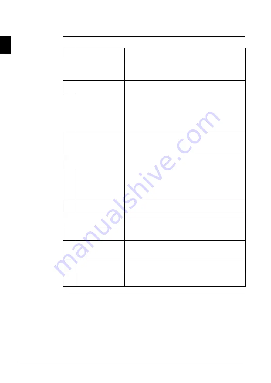
The table below describes the components.
No.
Component
Function / remark
1
Compressor
A hermetically sealed scroll compressor.
2
Water-heat exchanger
(evaporator))
The water-heat exchanger is of the brazed plate-heat exchanger
type.
3
Expansion valve
The thermostatic expansion valve is set up to control the
superheat between 5°C and 7°C.
4
Low-pressure switch
This switch acts as a circuit safety.
■
Standard setting: OFF = 1.2 bar ± 0.2
■
Standard setting: ON = 2 bar ± 0.3
■
ZL/ZH setting: OFF = 0.5 bar ± 0.2
■
ZL/ZH setting: ON = 1.5 bar ± 0.3
5
High-pressure switch
This switch acts as a circuit safety.
■
Standard setting: OFF = 30.9 bar +0/-1
■
Standard setting: ON = 21.6 bar ± 0.1
6
Strainer
This strainer prevents dirt particles from entering the expansion
valve.
7
Water in- and outlet
connections
The water in- and outlet connections are made of galvanized
steel pipe (British Standard Pipe - BSP). The pipes are not
insulated.
If copper field piping is used for the water circuit, then precau-
tion should be taken to prevent electrolytic corrosion.
8
Low-pressure
service port
The low-pressure service port is used to connect a
low-pressure gauge.
9
Sight glass with
moisture indicator
10
Water temperature
sensor
The water temperature sensors are used to control the
thermostat function at the heat exchanger inlet.
11
Freeze-up sensor
This protection device shuts down the circuit when the tempera-
ture of the chilled water becomes too low in order to prevent the
water from freezing during operation.
12
Accumulator
The accumulator is used to prevent the liquid refrigerant from
entering the compressor.
13
Liquid solenoid valve
The liquid solenoid valve prevents that that the evaporator fills
up with liquid if the unit is switched off.
Содержание EUWL KZW1 Series
Страница 1: ......
Страница 2: ......
Страница 8: ...Introduction ESIE 0303 vi 3 1 4 5 ...
Страница 10: ...ESIE 0303 1 2 Part 1 System Outline 3 1 1 5 ...
Страница 50: ...Piping Layout ESIE 0303 1 42 Part 1 System Outline 3 1 1 4 5 ...
Страница 60: ...Wiring Layout ESIE 0303 1 52 Part 1 System Outline 3 1 1 4 5 ...
Страница 61: ...ESIE 0302 Wiring Layout Part 1 System Outline 1 53 3 6 Wiring Diagram Wiring diagram ...
Страница 62: ...Wiring Layout ESIE 0302 1 54 Part 1 System Outline ...
Страница 64: ...ESIE 0303 2 2 Part 2 Functional Description 3 1 2 5 ...
Страница 82: ...The Digital Controller EUW5 24KZW1 and EUWL5 24KZW1 ESIE 0303 2 20 Part 2 Functional Description 3 1 2 4 5 ...
Страница 84: ...ESIE 0303 3 2 Part 3 Troubleshooting 3 1 3 5 ...
Страница 87: ...ESIE 0303 Inputs and Outputs Overview Part 3 Troubleshooting 3 5 3 3 4 5 1 ...
Страница 88: ...Inputs and Outputs Overview ESIE 0303 3 6 Part 3 Troubleshooting 3 1 3 4 5 ...
Страница 94: ...Malfunction Indications and Safeties Overview ESIE 0303 3 12 Part 3 Troubleshooting 3 1 3 4 5 ...
Страница 100: ...Checking the Inputs and Outputs ESIE 0303 3 18 Part 3 Troubleshooting 3 1 3 4 5 ...
Страница 112: ...Troubleshooting ESIE 0303 3 30 Part 3 Troubleshooting 3 1 3 4 5 ...
Страница 114: ...ESIE 0303 4 2 Part 4 Commissioning and Test Run 3 1 4 5 ...
Страница 130: ...ESIE 0303 5 2 Part 5 Maintenance 3 1 5 ...
Страница 139: ...ESIE 0303 Index 3 3 4 5 1 Wiring Diagram k 1 53 ...
Страница 140: ...ESIE 0303 4 Index 3 1 4 5 ...