background image

Installation manual

33

EKHBRD011~Y1

Indoor unit for air to water heat pump system

4PW54465-1C

M

AINTENANCE


AND


SERVICE

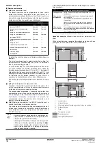
In order to ensure optimal availability of the unit, a number of checks
and inspections on the unit and the field wiring have to be carried out
at regular intervals.

This maintenance should be carried out by your local Daikin
technician.

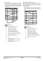
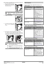
To  execute the maintenance
activities as mentioned below, it
is only required to remove the
front decoration panel.

To take away the front decoration
panel, remove the 2 bottom
screws and then unhitch the
panel.

Maintenance activities

The described checks must be executed at least once a year  by
qualified personnel.

1

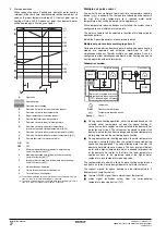
Water pressure relief valve

Check for correct operation of the pressure relief valve by
turning the red knob on the valve counter-clockwise:

If you do not hear a clacking sound, contact your local dealer.

In case the water keeps running out of the unit, close both
the water inlet and outlet shut-off valves first and then contact
your local dealer.

2

Pressure relief valve hose

Check that the pressure relief valve hose is positioned
appropriately to drain the water.

3

Indoor unit switch box

Carry out a thorough visual inspection of the switch box and look
for obvious defects such as loose connections or defective
wiring.

4

Water pressure

Check if the water pressure is above 1 bar.

If necessary add water.

5

Water filter

Clean the water filter.

T

ROUBLESHOOTING

This section provides useful information for diagnosing and
correcting certain troubles which may occur in the unit.

This troubleshooting and related corrective actions may only be
carried out by your local Daikin technician.

General guidelines

Before starting the troubleshooting procedure, carry out a thorough
visual inspection of the unit and look for obvious defects such as
loose connections or defective wiring.

When a safety device was activated, stop the unit and find out why
the safety device was activated before resetting it. Under no
circumstances safety devices may be bridged or changed to a value
other than the factory setting. If the cause of the problem can not be
found, call your local dealer

.

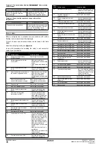
If the pressure relief valve is not working correctly and is to be
replaced, always reconnect the flexible hose attached to the pressure
relief valve, to avoid water dripping out of the unit!

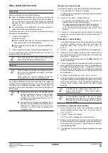
Opening the unit

To facilitate access to the air
purge valve, thermal cut-out,
3-way valve, thermistors,
field wiring duct, ..., the top
decoration panel of the unit
can be removed by
removing the 2 screws at the
rear and then unhitch the
panel.

In combination with
removing the top decoration
panel, the front decoration
panel can also be removed
to allow servicing the
manometer, pressure relief
valve, ... To remove the front
decoration panel, remove
the 2 bottom screws and
then unhitch the panel.

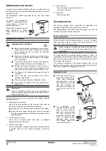
WARNING: ELECTRIC SHOCK 

Before carrying out any maintenance or repair activity,
always switch off the circuit breaker on the supply
panel, remove the fuses or open the protection
devices of the unit.

Make sure that before starting any maintenance or
repair activity, also the power supply to the outdoor
unit is switched off.

Do not touch live parts for 10 minutes after the power
supply is turned off because of high voltage risk.

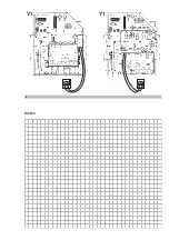
Additionally, measure the points as shown in 

figure 5

with a tester and confirm that the voltage of the
capacitor in the main circuit is no more than 50 V DC.

The heater of the compressor may operate even in
stop mode.

Please note that some sections of the electric
component box are hot.

Make sure you do not touch a conductive section.

Do not rinse the indoor unit. This may cause electric
shocks or fire.

Play it safe!

Touch a metal part by hand (such as the stop valve) in
order to eliminate static electricity and to protect the PCB
before performing service.

2x

When carrying out an inspection on the switch box of the
unit, always make sure that the main switch of the unit is
switched off.

2x

4x

2x

Содержание EKHBRD-AY1

Страница 1: ...INSTALLATION MANUAL EKHBRD011AAV1 EKHBRD014AAV1 EKHBRD016AAV1 EKHBRD011AAY1 EKHBRD014AAY1 EKHBRD016AAY1 Indoor unit for air to water heat pump system...

Страница 2: ...15 15 4 38 60 74 694 465 381 120 611 62 16 14 15 13 13 15 132 80 447 180 100 11 12 11 12 8 6 2 1 9 10 10 9 9 9 7 3 5 13 13 PS LV HV HV LV PS LV HV PS LV LV LV 1x 1x 1x 2x 1x 1x 1x 1x 1 2 3 4 6 2x 7 2x...

Страница 3: ...des 04 overeenkomstig de bepalingen van 05 siguiendo las disposiciones de 06 secondo le prescrizioni per 07 v v v 08 de acordo com o previsto em 09 10 under iagttagelse af bestemmelserne i 11 enligt...

Страница 4: ...ou for purchasing this unit The unit is the indoor part of the air to water ERSQ or ERRQ heat pump The unit is designed for floor standing indoor installation and used for heating applications The uni...

Страница 5: ...w are for illustration purposes only Application 1 Space heating and domestic hot water heating with a single remote controller installed in the living room The remote controller gives immediate feedb...

Страница 6: ...mer operation 1 Outdoor unit 10 Collector field supply 2 Indoor unit 11 Radiator field supply 3 Refrigerant heat exchanger 12 Electronic expansion valve 13 By pass valve field supply 4 Water heat exch...

Страница 7: ...er distribution is in this case the responsibility of the installer Pattern B The domestic hot water tank is installed in a separate circuit with a 3 way valve of the temperature reducing device s Thi...

Страница 8: ...rmostat C Auxiliary contact normal closed th Heating only room thermostat K1A Auxiliary relay for activation of EKHBRD unit field supply K2A Auxiliary relay for activation of boiler field supply NOTE...

Страница 9: ...from the water to prevent damage to the pump or blockage of the evaporator The water filter must be cleaned on a regular base See Maintenance activities on page 33 12 Expansion vessel 12 l 13 Manomete...

Страница 10: ...ry 20 Interface relay K1A 21 Wiring bridges 22 Fuse F1 only Y1 23 Fuse F2 only Y1 Functional diagram 8 18 12 20 13 2 3 1 19 5 10 14 11 17 16 15 21 6 9 7 15 15 8 18 12 20 13 2 3 1 19 10 7 14 11 17 16 2...

Страница 11: ...e carrier claims agent Bring the unit as close as possible to its final installation position in its original package in order to prevent damage during transport Unpack the indoor unit completely acco...

Страница 12: ...ter on page 13 Perform the electrical wiring work as described in the chapter Electrical wiring work on page 13 To make the casing completely sealed plug the knockout holes with putty or insulation ma...

Страница 13: ...instructions mentioned on the top plate of the unit In case of right connection only 2 pipes are required In case of left connection the 4 pipes are required Guidelines for flare connection Flares sh...

Страница 14: ...ains possible Take care that the components installed in the field piping can withstand the water pressure and temperature Always use materials which are compatible with the water used in the system a...

Страница 15: ...this must be done is explained in the chapter Opening the unit on page 33 Connecting the water circuit Water connections must be made The location of the water inlet connection and the water outlet c...

Страница 16: ...ations Be sure to install the required fuses as mentioned on the electrical wiring diagram The field wiring must be carried out in accordance with the wiring diagram supplied with the unit and the ins...

Страница 17: ...R2 A4P Resistance R1L Reactor R1L R3L Reactor R1H EKRTR Humidity sensor optional R1T EKRTW R Ambient sensor optional R2T EKHTS Domestic hot water tank thermistor optional R2T EKRTETS External sensor...

Страница 18: ...er supply switch S1S a 2 2 100 mA c 9 LV Multiple set point signal 1 a 2 2 100 mA c 10 LV Multiple set point signal 2 a 2 2 100 mA c 11 LV Heater kit signal a Refer to the installation manual of the h...

Страница 19: ...lectricity during certain periods of time The indoor unit is designed to receive an input signal by which the unit switches into forced off mode At that moment the unit compressors will not operate Po...

Страница 20: ...ck the switch box and the inside of the unit on loose connections or damaged electrical components 5 Installation Check that the unit is properly installed to avoid abnormal noises and vibrations when...

Страница 21: ...the Field settings table on page 30 In this list we provided for 2 columns to register the date and value of altered field settings at variance with the default value A detailed description of each fi...

Страница 22: ...emperature set points When setback function is enabled the setback operation will have priority over the scheduled action in the schedule timer Permission level 2 level 3 Operation ON OFF Operable Ope...

Страница 23: ...at the next scheduled ON function The last programmed command overrules the preceding programmed command and will remain active until the next programmed command occurs Example imagine the actual time...

Страница 24: ...temperature equals or rises above the high ambient temperature Hi_A Note that the Hi_Ti value should be lower than Lo_Ti as for warmer outdoor temperatures i e Hi_A less warm water suffices 4 Disinfec...

Страница 25: ...ol on page 27 8 Option setup 8 00 Remote controller temperature control When using the remote control delivered with the unit 2 types of temperature control are possible Default 8 00 1 which means tha...

Страница 26: ...hot water to the domestic hot water tank if the reheat minimum value is reached The domestic water heating will continue until the reheat maximum temperature is reached In this way always a minimum of...

Страница 27: ...o 1 to enable the vacuum mode E 04 Pump only operation When commissioning and installing the unit it is very important to get all air out of the water circuit Through this field setting the pump can b...

Страница 28: ...tic hot water tank temperature D Leaving water thermo on request F Domestic hot water lower limit temperature G Domestic hot water upper limit temperature maximum possible storage temperature b 03 H D...

Страница 29: ...oom temperature thermo on request E Remote controller room temperature F Domestic hot water lower limit temperature G Domestic hot water upper limit temperature maximum possible storage temperature b...

Страница 30: ...estic hot water tank coil is open The heat pump will deliver water with a higher temperature which is needed for production of the domestic hot water At that time the lower temperature appliances have...

Страница 31: ...nt of course is higher than 70 C b 03 OFF ON OFF OFF OFF Space 1 65 C A 03 OFF ON OFF ON ON OFF Space 2 35 C A 04 OFF ON OFF ON OFF ON Resulting heat pump water OFF 70 C 65 C 65 C 35 C NOTE If the sys...

Страница 32: ...ng Thermo status Space 0 65 C Remote controller OFF ON OFF OFF OFF Space 1 45 C A 03 OFF ON OFF ON ON OFF Space 2 35 C A 04 OFF ON OFF OFF ON ON Resulting heat pump water OFF 65 C 45 C 45 C 35 C NOTE...

Страница 33: ...ambient temperature Lo_Ti 70 25 80 1 C 03 Set point at high ambient temperature Hi_Ti 45 25 80 1 C 4 Disinfection function 00 Status disinfection operation 1 ON 0 1 01 Disinfection operation day selec...

Страница 34: ...tatus weather dependent domestic water heating 1 ON 0 1 03 Set point storage temperature 70 45 75 1 C C Leaving water temperature limits 00 Set point leaving water maximum temperature 80 37 80 1 C 01...

Страница 35: ...ws when no action is performed the user interface will return to normal mode after 10 seconds or by pressing the z button once To test the space heating operation push the y button to start the test r...

Страница 36: ...ice was activated stop the unit and find out why the safety device was activated before resetting it Under no circumstances safety devices may be bridged or changed to a value other than the factory s...

Страница 37: ...on the manometer that there is sufficient water pressure The water pressure must be 0 3 bar water is cold 0 3 bar water is hot Make sure that the expansion vessel is not broken The water volume in the...

Страница 38: ...roller thermostat thermistor error Contact your local dealer E1 Compressor PCB error Contact your local dealer E3 High pressure error S1PH Check wiring connections on outdoor unit and indoor unit Make...

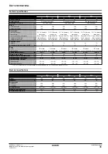
Страница 39: ...8 inch 15 9 5 8 inch 15 9 5 8 inch 15 9 5 8 inch 15 9 5 8 inch 15 9 5 8 inch Expansion vessel volume l 12 12 12 12 12 12 maximum working pressure MWP bar 4 4 4 4 4 4 Pump type DC motor DC motor DC mo...

Страница 40: ...t 7 02 1 and 7 03 1 or and 7 04 1 6 01 1 page 22 What type of appliance do you have No Blank display Push the b button n You selected permission level 3 on remote controller 0 00 3 page 19 You selecte...

Страница 41: ...tion function will operate depending on settings request w icon will start blinking with 0 5 second intervals Domestic hot water production will start immediately w icon will start blinking with 1 sec...

Страница 42: ...nue in domestic hot water External room thermostat contol Yes Yes Yes 2 No Operation will switch to space heating Operation will switch to space heating Timer d 02 15 minutes passed sicne 2 No Space h...

Страница 43: ...V1 Y1 NOTES 5 5...

Страница 44: ...4PW54465 1C Copyright Daikin...

Отзывы: