manualshive.com logo in svg
background image

Installer reference guide

Daikin Altherma low temperature monobloc

English

Installer reference guide

Daikin Altherma low temperature monobloc

07CAV3   
07CAV3   
                        
EKCB07CAV3   
EK2CB07CAV3    
                   
EKMBUHCA3V3   
EKMBUHCA9W1

Содержание EBLQ05+07CAV3

Страница 1: ...r reference guide Daikin Altherma low temperature monobloc English Installer reference guide Daikin Altherma low temperature monobloc EBLQ05 07CAV3 EDLQ05 07CAV3 EKCB07CAV3 EK2CB07CAV3 EKMBUHCA3V3 EKM...

Страница 2: ...l temperature sensor 23 6 Preparation 24 6 1 Overview Preparation 24 6 2 Preparing installation site 24 6 2 1 Installation site requirements of the outdoor unit 24 6 2 2 Additional installation site r...

Страница 3: ...Overview Commissioning 75 9 2 Precautions when commissioning 75 9 3 Checklist before commissioning 75 9 4 Checklist during commissioning 75 9 4 1 To check the minimum flow rate 75 9 4 2 Air purge func...

Страница 4: ...hildren can play with them Possible risk suffocation DANGER RISK OF BURNING Do NOT touch the refrigerant piping water piping or internal parts during and immediately after operation It could be too ho...

Страница 5: ...ype of refrigerant and necessary amount The unit is factory charged with refrigerant and depending on pipe sizes and pipe lengths some systems require additional charging of refrigerant Only use tools...

Страница 6: ...h electrical component and terminal inside the electrical components box is connected securely Make sure all covers are closed before starting up the unit NOTICE Only applicable if the power supply is...

Страница 7: ...de This table has to be filled in by the installer and handed over to the user 3 About the box 3 1 Overview About the box This chapter describes what you have to do after the boxes with the outdoor un...

Страница 8: ...he accessories from the control box 1 Open the control box 2 Remove the accessories 2 2 2 a b c a M4 bolts for user interface b M4 nuts for user interface c Wires for domestic hot water booster heater...

Страница 9: ...unit with options Combining the control box with options Possible combinations of outdoor unit and control box 4 2 Identification NOTICE When installing or servicing several units at the same time mak...

Страница 10: ...Refrigerant part of the outdoor unit c Hydro part of the outdoor unit d Valve kit EKMBHBP1 e Backup heater kit EKMBUHCA3V3 or EKMBUHCA9W1 f Control box EKCB07CAV3 g Option box EK2CB07CAV3 h Domestic h...

Страница 11: ...or providing domestic hot water a domestic hot water tank can be connected to the outdoor unit The domestic hot water tank is available in 2 types Stainless steel tank EKHWS and EKHWSU only for UK The...

Страница 12: ...ed as room temperature sensor As an option the remote indoor sensor can be installed to measure the room temperature on another location The remote indoor sensor is connected to option box EK2CB07CAV3...

Страница 13: ...dditional external room thermostat Highest comfort and efficiency The smart room thermostat functionality can decrease or increase the desired leaving water temperature based on the actual room temper...

Страница 14: ...ooling The heat pump convector offers besides heating capacity also excellent cooling capacity Efficiency Optimal energy efficiency because of the interlink function Stylish Combination Under floor he...

Страница 15: ...Fireplaces Configuration Setting Value Unit temperature control A 2 1 7 Code C 07 2 RT control Unit operation is decided based on the ambient temperature of the user interface Number of water tempera...

Страница 16: ...r interface b Control box c Backup heater option d External room thermostat e Remote controller of the heat pump convectors For each room with heat pump convectors The heat pump convectors are directl...

Страница 17: ...or unit or to the backup heater if there is one The desired room temperature is set via the remote controller of the heat pump convectors for each room The heating or cooling demand signals of each he...

Страница 18: ...ating NOTICE Make sure the auxiliary boiler and its integration in the system complies with applicable legislation Daikin is NOT responsible for incorrect or unsafe situations in the auxiliary boiler...

Страница 19: ...ble DHW tank volumes Type Possible volumes Standalone DHW tank 150 l 200 l 300 l Energy saving tips If the DHW consumption differs from day to day you can program a weekly schedule with different desi...

Страница 20: ...estic hot water pump on page 43 and the installation manual of the domestic hot water tank Configuration For more information see 8 Configuration on page 48 You can program a schedule to control the D...

Страница 21: ...14 Technical data on page 86 When using electrical power meters set the number of pulses kWh for each power meter via the user interface INFORMATION When measuring the electrical power consumption mak...

Страница 22: ...ou to limit the power consumption of the entire system sum of the outdoor unit control box EKCB07CAV3 option box EK2CB07CAV3 the backup heater kit and the optional booster heater Configuration Set the...

Страница 23: ...d at the same time the digital input priority is fixed DI4 priority DI1 5 6 3 Power limitation process The outdoor unit has better efficiency than the electrical heaters Therefore the electrical heate...

Страница 24: ...rying the unit in and out of the site 6 2 1 Installation site requirements of the outdoor unit INFORMATION Also read the precautions and requirements in the General safety precautions chapter Mind the...

Страница 25: ...between control box and outdoor unit 20 m Maximum distance between control box and backup heater kit 10 m Maximum distance between control box and domestic hot water tank 10 m Mind the following spaci...

Страница 26: ...dust If air moisture or dust gets into the circuit problems may occur To prevent this Only use clean pipes Hold the pipe end downwards when removing burrs Cover the pipe end when inserting it through...

Страница 27: ...unit and will NOT be removed by the standard filter of the heat pump system Domestic hot water tank Capacity To avoid stagnation of water it is important that the storage capacity of the domestic hot...

Страница 28: ...e water circuit and the outdoor unit If the outdoor unit is at the highest point of the installation the installation height is 0 m b The maximum water volume is 185 l in case the circuit is only fill...

Страница 29: ...wer supply cables 6 4 2 About preferential kWh rate power supply Electricity companies throughout the world work hard to provide reliable electric service at competitive prices and are often authorize...

Страница 30: ...r supply for control box 2 GND a Item Description Wires Maximum running current Interconnection cable 7 Interconnection cable between outdoor unit and control box 2 b 8 Interconnection cable for the u...

Страница 31: ...different connections are indicated on the inside of the units outdoor unit control box option box and backup heater For how to connect the electrical wiring to the outdoor unit and if part of the sys...

Страница 32: ...are delivered with toothed lock washers ALWAYS use toothed lock washers also when the screws need to be replaced Failure to follow this warning may result in electric shock INFORMATION Do NOT remove t...

Страница 33: ...ORMATION For information on the available options contact your dealer If the unit is installed directly on the floor prepare 4 sets of M8 or M10 anchor bolts nuts and washers field supply as follows I...

Страница 34: ...heet NOTICE To prevent damage to the supporting feet do NOT tilt the unit sideways in any way 7 3 5 To provide drainage Avoid installation places where water leaking from the unit due to a blocked dra...

Страница 35: ...tching the paint field supply 4 Attach the cable s ends Tighten those ends 7 4 Mounting the control box 7 4 1 About mounting the control box 7 4 2 Precautions when mounting the control box INFORMATION...

Страница 36: ...nly be connected to the space heating water outlet of the outdoor unit Other connections are NOT allowed Only one backup heater can be connected to the outdoor unit It is NOT allowed to combine multip...

Страница 37: ...stalled on the cold water inlet connection of the domestic hot water cylinder To avoid back siphonage it is recommended to install a non return valve on the water inlet of the domestic hot water tank...

Страница 38: ...tem does NOT contain a domestic hot water tank You can use either propylene glycol a or ethylene glycol a Propylene glycol including the necessary inhibitors classified as Category III according to EN...

Страница 39: ...piping and shut off valves against freezing by adding heat tape field supply If the outdoor temperature can drop below 20 C and no heat tape is used it is recommended to install the shut off valves in...

Страница 40: ...rews A screwdriver with a small head will damage the head and make proper tightening impossible Over tightening the terminal screws may break them Tightening torques Item Tightening torque N m M4 X1M...

Страница 41: ...X6YA X19A X2M X8M S1S b a c 1 GND 2 L 3 N a Interconnection cable main power supply b Normal kWh rate power supply c Preferential power supply contact on the control box INFORMATION For the exact pos...

Страница 42: ...terface you can connect it onto control box EKCB07CAV3 for control close to the control box or in the room where used as room thermostat If you use 2 user interfaces you can connect 1 user interface o...

Страница 43: ...n 4A From the rear b a PCB 1 4B From the left a PCB b 1 4C From the top a b PCB b 1 4D From the top centre a PCB b b 1 a Notch this part for the wiring to pass through with nippers etc b Secure the wi...

Страница 44: ...the cable tie mountings to ensure strain relief and to make sure that it does NOT come in contact with sharp edges CAUTION Do NOT push or place redundant cable length in the unit 7 8 12 To connect th...

Страница 45: ...V3 INFORMATION In case of an electrical meter with transistor output check the polarity The positive polarity MUST be connected to X2M 7 and X2M 9 the negative polarity to X2M 8 and X2M 10 1 Connect t...

Страница 46: ...kit thermistor interconnection with control box EKCB07CAV3 Backup heater kit thermal protector interconnection with control box EKCB07CAV3 Backup heater kit connection to control box EKCB07CAV3 b Hig...

Страница 47: ...used for F1B For 9W models a 4 pole fuse is used for F1B 2 If required modify the connection on terminal X14M Backup heater type Connections to backup heater power supply Connections to terminals 3 kW...

Страница 48: ...over make sure that the tightening torque does NOT exceed 4 1 N m 7 10 Finishing the control box installation 7 10 1 To close the control box 1 Close the front plate 7 11 Finishing the option box inst...

Страница 49: ...level to Installer 2 Go to A 8 Installer settings Overview settings To set the user permission level to Installer 1 Set the user permission level to Adv end user 2 Go to 6 4 Information User permissi...

Страница 50: ...a the user interface you are operating contains the correct data and the data on the other user interface will be overwritten Receive data the user interface you are operating does NOT contain the cor...

Страница 51: ...cordingly Code Description A 2 1 7 C 07 Unit control method 0 LWT control Unit operation is decided based on the leaving water temperature regardless the actual room temperature and or heating or cool...

Страница 52: ...b c a Space heating cooling control user interface b OFF c On d LWT temperature e Actual f Desired g Pump operation continued Code Description A 2 1 9 F 0D continuation 2 Request default Pump operati...

Страница 53: ...set See 5 Application guidelines on page 12 0 No default NOT installed The thermistor in the user interface and in the outdoor unit are used for measurement 1 Outdoor sensor Remote outdoor sensor con...

Страница 54: ...5 Application guidelines on page 12 1 Thermo ON OFF See Contact type main Connected on the indoor unit X2M 1a 2 N A If there are two zones main additional then only Thermo ON OFF is possible Option b...

Страница 55: ...at nominal voltage Nominal value is 3 kW Default 3 kW Range 0 10 kW in steps of 0 2 kW A 2 3 2 6 03 BUH step 1 The capacity of the first step of the backup heater at nominal voltage Nominal value 3 kW...

Страница 56: ...e control Code Description 7 7 1 1 1 00 1 01 1 02 1 03 Set weather dependent heating 1 03 1 02 Ta Tt 1 00 1 01 Tt Target leaving water temperature main Ta Outdoor temperature continued Code Descriptio...

Страница 57: ...water temperature Additional zone Only applicable if 2 leaving water temperature zones are present Code Description A 3 1 2 1 N A LWT setpoint mode Fixed default The desired leaving water temperature...

Страница 58: ...perature when the outdoor temperature equals or rises above the high ambient temperature Between minimum and maximum leaving water temperature 9 07 9 08 default 8 C Note This value should be lower tha...

Страница 59: ...imum setpoint Refer to the illustration below a 8 06 8 06 b Ta Tt a Weather dependent curve b Minimum leaving water temperature setpoint required to reach a stable condition on the comfort setpoint fo...

Страница 60: ...4 8 08 Eco cooling 9 03 9 02 default 20 C Preset leaving water temperature shift value for the main leaving water temperature zone in case of weather dependent Code Description 7 4 2 5 N A Comfort hea...

Страница 61: ...n the desired leaving water temperature decided on the difference between the actual and desired room temperature e g 3 C modulation means the desired leaving water temperature can be increased or low...

Страница 62: ...room thermostat control C 07 1 Allow for the external room thermostat to take care of room frost protection Turn ON the leaving water temperature home page Set auto emergency A 5 1 2 to 1 Leaving wate...

Страница 63: ...he leaving water temperature setpoint will be lowered by 5 C When the leaving water temperature home page is ON and the operation mode is heating then the unit will supply leaving water to the heat em...

Страница 64: ...default 3 C 8 3 2 Domestic hot water control advanced Preset tank temperatures Only applicable when domestic hot water preparation is scheduled or scheduled reheat You can define preset tank temperatu...

Страница 65: ...e and domestic hot water over the complete heating season If the outdoor temperature is below setting 5 03 and 5 02 1 the domestic hot water will not be heated The domestic hot water temperature can b...

Страница 66: ...thermostat control This preset value is only taken into account if there is a request for space heating or cooling If there is NO request for space heating cooling the tank is heated until the setpoi...

Страница 67: ...p will be equal to the value selected in field setting 2 03 after a disinfection operation When the high domestic hot water temperature can be a potential risk for human injuries a mixing valve field...

Страница 68: ...ntire heat load or whether manual confirmation is required 0 Manual default 1 Automatic INFORMATION The auto emergency setting can be set in the menu structure of the user interface only INFORMATION I...

Страница 69: ...T be held liable for any damage resulting from failure to observe this rule INFORMATION The combination of setting 4 03 0 2 with bivalent operation at low outdoor temperature can result in domestic ho...

Страница 70: ...nable the auto restart function 2 The refrigerant part of the outdoor unit is connected to a preferential kWh rate power supply When the preferential kWh rate signal is sent by the electricity company...

Страница 71: ...20 kW Priority Only applicable in case of an optional EKHW Code Description A 6 3 7 4 01 Power consumption control DISABLED 4 08 0 0 None default Backup heater and booster heater can operate simultan...

Страница 72: ...led the pump operation is possible at all outdoor temperatures Code Description N A F 00 Pump operation 0 Disabled if outdoor temperature is higher than 4 02 or lower than F 01 depending on heating co...

Страница 73: ...handling User permission level Actuators Operation modes Running hours Version Energy metering Consumed elec Produced energy Error information Error history Contact helpdesk number Version User interf...

Страница 74: ...pressor type Indoor software type Unit control method Number of LWT zones Pump operation mode Power saving possible User interface location Options DHW pump External sensor Control box Option box Leav...

Страница 75: ...ment and have not been bypassed The power supply voltage matches the voltage on the identification label of the unit There are NO loose connections or damaged electrical components in the switch box T...

Страница 76: ...he home screens and that the space heating and domestic hot water demands are turned off The air purge function automatically stops after 30 minutes To perform a manual air purge Prerequisite Make sur...

Страница 77: ...actuator test runs Booster heater test Backup heater step 1 test Backup heater step 2 test Pump test INFORMATION Make sure that all air is purged before executing the test run Also avoid disturbances...

Страница 78: ...06 0 By default it is enabled 2 06 1 However due to the installer on site mode see Checklist before commissioning room frost protection will be automatically disabled for 12 hours after the first pow...

Страница 79: ...seconds 11 Maintenance and service NOTICE Maintenance should preferably be carried out yearly by an installer or service agent 11 1 Overview Maintenance and service This chapter contains information a...

Страница 80: ...n open position when the power is turned OFF WARNING If the internal wiring is damaged it has to be replaced by the manufacturer its service agent or similarly qualified persons Booster heater of the...

Страница 81: ...ture is too low the unit uses the backup heater to reach the minimum water temperature first 15 C Check and make sure that The power supply to the backup heater is correctly wired The backup heater th...

Страница 82: ...s on page 92 for the location of the reset button Possible causes Corrective action If the system contains a backup heater the backup heater equilibrium temperature has not been configured correctly I...

Страница 83: ...licensed installer or by your local dealer This chapter gives you an overview of all error codes and the content of the error code as it appears on the user interface For a more detailed troubleshoot...

Страница 84: ...Auto restart 7H 04 Water flow problem during domestic hot water production Manual reset Check the domestic hot water circuit 7H 05 Water flow problem during heating sampling Manual reset Check the spa...

Страница 85: ...cuit Error code Detailed error code Description 7H 06 The water flow problems mainly occurred during cooling defrost operation Check the space heating cooling circuit Additionally this error code migh...

Страница 86: ...stop valve b Closing direction c Hexagonal wrench d Valve lid e Liquid stop valve 13 3 To start and stop forced cooling Confirm that DIP switch SW2 is in COOL mode 1 Press the forced cooling operation...

Страница 87: ...MBUHCA9W1 Daikin Altherma low temperature monobloc 4P405544 1 2015 03 14 2 Dimensions and service space 14 2 1 Dimensions and service space Outdoor unit Dimensions Outdoor unit 1089 356 304 735 44 75...

Страница 88: ...kin Altherma low temperature monobloc 4P405544 1 2015 03 14 2 2 Dimensions and service space Options Dimensions and service space control box and option box 50 50 50 100 600 50 340 97 55 360 318 340 2...

Страница 89: ...ata Installer reference guide 89 EBLQ05 07CAV3 EDLQ05 07CAV3 EKCB07CAV3 EK2CB07CAV3 EKMBUHCA3V3 EKMBUHCA9W1 Daikin Altherma low temperature monobloc 4P405544 1 2015 03 Service space backup heater 50 5...

Страница 90: ...ler reference guide 90 EBLQ05 07CAV3 EDLQ05 07CAV3 EKCB07CAV3 EK2CB07CAV3 EKMBUHCA3V3 EKMBUHCA9W1 Daikin Altherma low temperature monobloc 4P405544 1 2015 03 14 3 Center of gravity 14 3 1 Center of gr...

Страница 91: ...07CAV3 EDLQ05 07CAV3 EKCB07CAV3 EK2CB07CAV3 EKMBUHCA3V3 EKMBUHCA9W1 Daikin Altherma low temperature monobloc 4P405544 1 2015 03 14 3 2 Center of gravity Options Center of gravity control box and optio...

Страница 92: ...tdoor unit p c l m h k b a d e i n n n o o j f g a Water IN connection 1 M b Water OUT connection 1 M c Wiring intake power supply d Wiring intake high voltage wiring e Wiring intake low voltage wirin...

Страница 93: ...405544 1 2015 03 14 4 2 Components Switch box outdoor unit X7M TB1 A1P FU1 X5M A2P X6YB X4M X3M X6Y X6YA a b g h c b d i e f a Transformer b Connectors c Terminal block to heaters d Terminal block low...

Страница 94: ...EBLQ05 07CAV3 EDLQ05 07CAV3 EKCB07CAV3 EK2CB07CAV3 EKMBUHCA3V3 EKMBUHCA9W1 Daikin Altherma low temperature monobloc 4P405544 1 2015 03 14 4 3 Components Options Components control box and option box...

Страница 95: ...1 Daikin Altherma low temperature monobloc 4P405544 1 2015 03 Components backup heater h e e e f f e c d g g b a EKMBUHCA3V EKMBUHCA9W a Water IN connection 1 M b Water OUT connection 1 M c Air purge...

Страница 96: ...t water tank c Booster heater circuit breaker only for installations with a domestic hot water tank d Terminal block only for installations with a domestic hot water tank e Terminal block power supply...

Страница 97: ...CuT 6 4 CuT Discharge pipe thermistor Accumulator Compressor High pressure switch Muffler Muffler 4 way valve Pressure sensor Refrigerant flow Cooling Heating Liquid stop valveV Plate heat exchanger...

Страница 98: ...See the internal wiring diagram supplied with the unit on the inside of the outdoor unit switch box cover The abbreviations used are listed below Position in switch box hydro switch box A1P TR1 X 3 M...

Страница 99: ...5 X19A 3 X19A 1 X4M PE X4M N X4M L PCB3 PCB2 PCB1 GRN GRN GRN RED RED RED RED 1 S502 2 3 4 5 6 7 8 9 10 11 S503 1 2 3 4 5 S501 1 2 3 4 5 SW5 SW2 SW1 SW3 A 1 2 3 4 DB1 DB2 HL402 HN402 1 2 3 4 5 6 7 8 9...

Страница 100: ...BLK GRN YLW BLK WHT SA1 FU3 V2 HL1 HN1 30A V3 S10 3 2 1 MR30_A MR30_B 1 2 S20 S50 1 2 3 4 5 1 2 3 4 DP2 DP1 MR307 MR306 FU1 T3 15A V401 DB401 1 2 3 4 5 6 1 2 3 4 1 2 3 4 5 6 7 WHT YLW ORG BLU RED Y1E...

Страница 101: ...R FU2 KVR 2 2 1 1 1 2 1 2 X5A X8A X7A X21A K4R K6R X10A X14A X15A X18A 1 2 3 4 5 3 1 1 3 1 2 A1P TR1 M1P S1L N L GND PWM PE MS 3 t t t R3T R4T R1T X10A X1A X5M X3M X5Y A2P 4 3 4 3 2 1 2 1 X2M 23 X2M 2...

Страница 102: ...witch box Heatpump convector only for wireless On OFF thermostat 4D094176 1A_Page 8 User interface Remote user interface Option box DHW pump output Max load 2 A inrush 230 V AC 1 A continuous DHW pump...

Страница 103: ...xtension PCB control optional A5P User interface PCB A7P Receiver PCB wireless On OFF thermostat DS1 A4P DIP switch B1L Flow sensor E1H Backup heater element 1 kW E2H Backup heater element 2 kW E3H Ba...

Страница 104: ...Fuse S1NPH Pressure sensor S1PH Pressure switch high R1T PCB1 Thermistor discharge R2T PCB1 Thermistor heat exchange R3T PCB1 Thermistor air S2 S503 Connector LED A LED B Pilot lamp IPM1 Intelligent...

Страница 105: ...0 kW 4 75 kW 6 90 kW Cooling capacity Minimum 2 00 kW 2 50 kW Nominal 4 20 kW 5 40 kW Maximum Heating PI Nominal 1 13 kW 2 02 kW 1 13 kW 2 02 kW Cooling PI Nominal 1 80 kW 2 34 kW COP Nominal 3 58 3 4...

Страница 106: ...t Minimum 25 C DB Maximum 35 C DB Sound level Nominal Heating Sound power 61 dBA 62 dBA 61 dBA 62 dBA Sound pressure 2 48 dBA 49 dBA 48 dBA 49 dBA Nominal Cooling Sound power 63 dBA Sound pressure 48...

Страница 107: ...Wiring connections For power supply Quantity 3 Remark For connection with control box Quantity 8 Remark 2 wires minimum cable section 0 75 mm maximum length 20 m 2 wires minimum cable section 0 75 mm...

Страница 108: ...cal specifications control box and option box Options EKCB07CAV3 EK2CB07CAV3 Power supply Phase 1 Frequency 50 Hz Voltage 230 V Voltage range Minimum 10 Maximum 10 Fuses Recommended fuses 16 A Technic...

Страница 109: ...heater 15 10 25 45 50 55 25 25 20 15 A C DB B C A Outdoor temperature B Leaving water condensor temperature C Leaving water evaporator temperature Backup heater only operation No outdoor unit operatio...

Страница 110: ...hot water heating mode for current models in this manual 5 kW 7 kW 25 55 35 20 25 15 25 40 45 50 80 A C DB B C 25 55 35 20 25 15 25 40 45 50 80 48 5 A C DB B C A Outdoor temperature B Domestic hot wat...

Страница 111: ...0 E D B LQ07CAV3 A kPa B l min C A External static pressure B Water flow rate C Operation range Notes The operation area is extended to lower flow rates only in case the unit operates with heat pump o...

Страница 112: ...n perform or coordinate the required service to the product Installation manual Instruction manual specified for a certain product or application explaining how to install configure and maintain it Op...

Страница 113: ...1 8 Field settings table Applicable units BLQ05CAV3 DLQ05CAV3 BLQ07CAV3 DLQ07CAV3 Notes 1 B 2 D 4P405542 1 2015 03...

Страница 114: ...nt temp for LWT main zone cooling WD curve R W 9 03 9 02 C step 1 C 22 C 7 7 1 2 1 09 Set weather dependent cooling Leaving water value for high ambient temp for LWT main zone cooling WD curve R W 9 0...

Страница 115: ...temp heating R W 37 55 C step 1 C 55 C A 3 1 1 2 3 9 03 Temperature range Minimum temp cooling R W 5 18 C step 1 C 5 C A 3 1 1 2 4 9 02 Temperature range Maximum temp cooling R W 18 22 C step 1 C 22 C...

Страница 116: ...5 1 3 4 07 R W 0 No 1 Yes A 5 1 4 5 01 R W 15 35 C step 1 C 4 C System operation Auto restart A 6 1 3 00 R W 0 No 1 Yes Preferential kWh rate A 6 2 1 D 00 R W 0 None 1 BSH only 2 BUH only 3 All heater...

Страница 117: ...p for LWT add zone heating WD curve Leaving water value for low ambient temp for LWT add zone heating WD curve High ambient temp for LWT add zone heating WD curve Low ambient temp for LWT add zone hea...

Страница 118: ...8 8 06 R W 0 10 C step 1 C 3 C A 8 8 07 R W 9 03 9 02 step 1 C 18 C A 8 8 08 R W 9 03 9 02 step 1 C 20 C How to protect the water pipes from freezing Do not change this value Enable the second step o...

Страница 119: ...A 8 D 04 R W 0 No 1 Yes A 8 D 05 R W 0 Forced off 1 As normal A 8 D 07 0 A 8 D 08 R W 0 No 1 0 1 pulse kWh 2 1 pulse kWh 3 10 pulse kWh 4 100 pulse kWh 5 1000 pulse kWh What is the desired comfort ma...

Страница 120: ...Enabled A 8 F 01 R W 10 35 C step 1 C 20 C A 8 F 02 3 A 8 F 03 5 A 8 F 04 0 A 8 F 05 0 A 8 F 06 0 A 8 F 09 R W 0 Disabled 1 Enabled A 8 F 0A 0 A 8 F 0B 0 A 8 F 0C 1 A 8 F 0D R W 0 Continuous 1 Sample...

Страница 121: ......

Страница 122: ...4P405544 1 2015 03 Copyright 2015 Daikin...
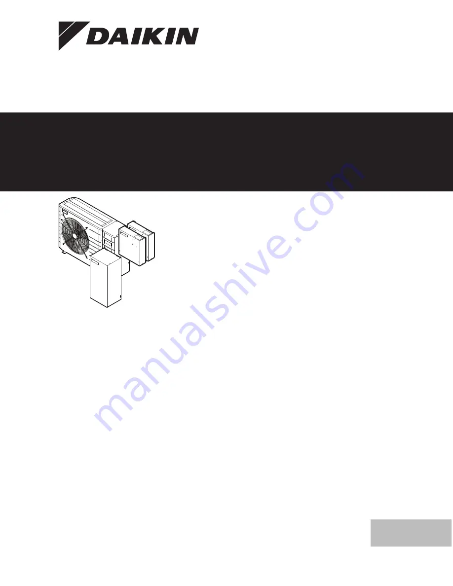
Отзывы: