background image

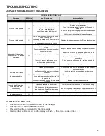
2 Stage Troubleshooting Codes

Symptom

LED Status

Fault Description

Corrective Actions

Normal operation



Normal operation

None

Locate and correct gas interruption

Replace or realign igniter

Check flame sense signal, clean sensor if coated or 

oxidized

Check flue piping for blockage, proper length, elbows, and 

termination

Verify proper induced draft blower performance

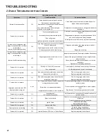
Low stage pressure switch circuit is closed at 

start of heating cycle

Low stage pressure switch contacts sticking

Short in pressure switch circuit wiring

Inspect flue for blockage, proper length, elbows, and 

termination

Check induced draft blower performance, correct as 

necessary

Check pressure switch operation, replace as needed

Tighten or correct wiring connection

Primary limit circuit is open

Check filters and ductwork for blockage Clean filters or 

remove obstruction

Insufficient conditioned air over the heat 

exchanger

Check circulator blower speed and performance

Blocked filters, restrictive ductwork, improper 

circulator blower speed, or failed circulator 

blower motor

Correct speed or replace blower motor if necessary

Loose or improperly connected wiring in high 

limit circuit

Tighten or correct wiring connection

Flame sensed with no call for heat

Correct short at flame sensor or in flame sensor wiring

Short to ground in flame sense circuit

Lingering burner flame Slow closing gas 

valve

Open fuse

Replace fuse

Short in low voltage wiring

Locate and correct short in low voltage wiring

Induced draft blower and 

circulator blower runs 

continuously

No furnace operation



Check for lingering or lazy flame Verify proper operation of 

gas valve

No furnace operation



TROUBLESHOOTING CHART

Induced draft blower  runs 

continuously with no furnace 

operation



Inspect pressure switch hose, repair/replace if necessary

Low stage pressure switch circuit is not 

closed 

Pressure switch hose blocked pinched, or 

connected improperly

Blocked flue pipe, or weak induced draft 

blower

Incorrect pressure switch set point or 

malfunctioning switch contacts

Loose or improperly connected wiring

Replace low stage pressure switch Repair short in wiring

Circulator blower runs 

continuously

No furnace operation



Furnace fails to operate



Furnace lockout due to an excessive number 

of ignition “retries” (3 total)

Failure to establish flame

Loss of flame after establishment

Furnace fails to operate



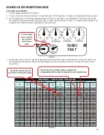
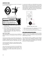
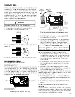
To View & Clear Fault Codes

• 

Press either the Left or Right switch until 

L 6 F

 is displayed. 

• 

Press the center switch to view stored faults.

• 

Press and hold the center switch for 5 to 30 seconds.

• 

All stored faults will be erased, and the display will flash - - - three times and return to 

L 6 F

.

TROUBLESHOOTING

41

Содержание DM80TN

Страница 1: ...ROPRIATE SERVICE MANUAL BEFORE BEGINNING REPAIRS Only personnel that have been trained to install adjust service or repair hereinafter service the equipment specified in this manual should service the...

Страница 2: ...after servicing WARNING FIRE EXPLOSION OR CARBON MONOXIDE POISONING HAZARD Failure to replace with proper control could result in fire explosion or carbon monoxide poisoning This appliance uses NEGATI...

Страница 3: ...ational Fuel Gas Code ANSI Z223 1 WARNING If not installed operated and maintained in accordance with the manufacturer s instructions this product could expose you to substances during fuel combustion...

Страница 4: ...259 216 El mon xido de carbono puede causar enfermedades severas como da o cerebral permanente muerte Las emisiones de mon xido de carbono pueden circular a trav s del aparato cuando se opera en cualq...

Страница 5: ...Initial Release B 1st Revision Configuration M Upflow Horizontal Major Revision C Downflow Horizontal A Initial Release B 1st Revision Nox AFUE 80 80 AFUE 92 92 AFUE 96 96 AFUE 97 97 AFUE Cabinet Widt...

Страница 6: ...d in accordance with local codes or in their absence with the latest edition of The National Electric Code ANSI NFPA 70 and or The Canadian Electric Code CSA C22 1 An electrical disconnect must be pro...

Страница 7: ...to high fire 1 Auto 2 Fixed Time Press the Left or Right menu switches to get to the A H S menu The menu will display these options no 10 20 30 60 AUt Fixed time options are expressed in minutes on t...

Страница 8: ...ating mounting grounding and controlling these accessories Accessory wiring connections are to be made through the 1 4 quick connect terminals provided on the furnace integrated control module The hum...

Страница 9: ...blower is energized When the thermostat is satisfied The gas valve is de energized The inducer remains energized for the post purge period 15 seconds The indoor blower runs for the selected off delay...

Страница 10: ...r the thermostat is satisfied the compressor is de energized and the Cool Mode Fan Off Delay period begins Following the Cool Mode Fan Off Delay period the cool circulator and air cleaner relay are de...

Страница 11: ...ACE BEFORE CHANGING SPEED TAPS WARNING CIRCULATING AIR AND FILTERS DUCTWORK AIR FLOW Duct systems and register sizes must be properly designed for the C F M and external static pressure rating of the...

Страница 12: ...500 1459 1419 1387 1349 1317 1286 F01 1036 985 940 895 848 799 751 705 F02 1391 1352 1314 1278 1241 1209 1175 1140 F03 710 646 580 515 432 367 314 274 F04 1138 1091 1045 1001 959 920 876 832 F05 1209...

Страница 13: ...156 1103 1037 982 932 878 F05 1811 1769 1730 1686 1649 1610 1572 1525 F06 1541 1487 1440 1395 1353 1310 1251 1203 F07 1587 1545 1494 1451 1409 1367 1316 1266 F08 1703 1659 1613 1579 1537 1495 1451 140...

Страница 14: ...544 1500 1459 1419 1387 1349 1317 1286 F01 1036 985 940 895 848 799 751 705 F02 1391 1352 1314 1278 1241 1209 1175 1140 F03 710 646 580 515 432 367 314 274 F04 1138 1091 1045 1001 959 920 876 832 F05...

Страница 15: ...07 1156 1103 1037 982 932 878 F05 1811 1769 1730 1686 1649 1610 1572 1525 F06 1541 1487 1440 1395 1353 1310 1251 1203 F07 1587 1545 1494 1451 1409 1367 1316 1266 F08 1703 1659 1613 1579 1537 1495 1451...

Страница 16: ...19 1387 1349 1317 1286 F01 1036 985 940 895 848 799 751 705 F02 1391 1352 1314 1278 1241 1209 1175 1140 F03 710 646 580 515 432 367 314 274 F04 1138 1091 1045 1001 959 920 876 832 F05 1209 1166 1124 1...

Страница 17: ...294 F04 1260 1207 1156 1103 1037 982 932 878 F05 1811 1769 1730 1686 1649 1610 1572 1525 F06 1541 1487 1440 1395 1353 1310 1251 1203 F07 1587 1545 1494 1451 1409 1367 1316 1266 F08 1703 1659 1613 1579...

Страница 18: ...4 928 F05 1588 37 1539 39 1494 40 1447 41 1401 42 1358 1313 1267 F01 1420 29 1359 31 1301 32 1254 33 1206 34 1152 1100 1044 F03 826 N A 744 N A 661 N A 573 N A 485 N A 399 339 N A F04 1623 N A 1567 N...

Страница 19: ...60 F01 1176 1105 1020 935 864 797 729 673 F02 1513 1459 1400 1335 1253 1182 1122 1067 F03 1022 813 674 585 511 431 334 282 F04 1640 1595 1540 1489 1436 1367 1307 1254 F05 1843 1786 1747 1690 1643 1575...

Страница 20: ...96 1160 F01 1176 1105 1020 935 864 797 729 673 F02 1513 1459 1400 1335 1253 1182 1122 1067 F03 1022 813 674 585 511 431 334 282 F04 1640 1595 1540 1489 1436 1367 1307 1254 F05 1843 1786 1747 1690 1643...

Страница 21: ...302 1267 1232 1196 1160 F01 1176 1105 1020 935 864 797 729 673 F02 1513 1459 1400 1335 1253 1182 1122 1067 F03 1022 813 674 585 511 431 334 282 F04 1640 1595 1540 1489 1436 1367 1307 1254 F05 1843 178...

Страница 22: ...N A 636 N A F04 1309 32 1261 33 1218 34 F02 1393 43 1348 44 1308 45 F04 1309 45 1261 47 1218 49 F05 1459 41 1414 42 1371 43 F01 1176 35 1105 38 1020 41 F03 1022 N A 813 N A 674 N A F04 1640 N A 1595...

Страница 23: ...N A 402 349 300 F04 1182 35 1142 36 1103 1064 1025 F02 1270 47 1230 48 1196 1158 1123 F04 1182 50 1142 52 1103 1064 1025 F05 1336 44 1297 46 1264 1229 1193 F01 935 44 864 48 797 729 673 F03 585 N A 5...

Страница 24: ...in 7 Secs increments from 0 to 35 Secs Cool Off Delay Delay Seconds Default set at 65 Secs Adjustments can be made in 5 Secs increments from 0 to 120 Secs Blower Speed for 1st Stage Gas Heat Mode xx...

Страница 25: ...SYSTEM OPERATION 25 2 Stage Status Codes Status Menu Idle Continous Fan Compressor Cooling Low Stage Compressor Cooling High Stage Gas heat Low Stage Gas heat High Stage OEM test Mode Mode Main Menu...

Страница 26: ...CAL COMPONENTS ARE CONTAINED IN BOTH COMPARTMENTS TO AVOID ELECTRICAL SHOCK INJURY OR DEATH DO NOT REMOVE ANY INTERNAL COMPARTMENT COVERS OR ATTEMPT ANY ADJUSTMENT CONTACT A QUALIFIED SERVICE AGENT AT...

Страница 27: ...2 164 327 655 1636 37 97 195 486 12 75 150 300 600 1500 38 23 47 95 189 474 13 69 138 277 555 1385 39 92 185 462 14 64 129 257 514 1286 40 22 45 90 180 450 15 60 120 240 480 1200 41 176 439 16 56 113...

Страница 28: ...he gas valve turn downward clockwise to increase pressure and input and upward counterclockwise to decrease pressure and input A properly operating unit must have the BTU per hour input and CFM of air...

Страница 29: ...king Auxiliary Limit Control 34 S 302 Checking Flame Rollout Control 35 S 303 Induced Draft Blower Motor 36 S 304 Checking Gas Valve Redundant 36 S 305 Checking Main Burners 36 S 306 Checking Orifices...

Страница 30: ...tely 144 volts out of phase reverse low voltage wires NOTE For flame rectification the common side of the secondary voltage 24 V is cabinet grounded If you were to bench test a transformer the primary...

Страница 31: ...king Thermostat And Wiring DISCONNECT ALL POWER BEFORE SERVICING WARNING 1 Remove the blower compartment door to gain access to the thermostat low voltage wires located at the furnace integrated contr...

Страница 32: ...T1 T5 wires on the control board Green ground wire connected to cabinet ground The control harness has The nine speed ECM motor requires a line voltage power supply black connected to CIRC H and white...

Страница 33: ...urnace as possible Thermometers must not be influenced by radiant heat by being able to see the heat exchanger SUPPLY AIR RETURN AIR Checking Temperature Rise 3 Subtract the return air temperature fro...

Страница 34: ...sh ELEVEN times If the limit circuit opens and does not close within fifteen minutes the control assumes the manual rollout or fuse has opened and the RED LED will flash FIVE times The control will en...

Страница 35: ...ut occur An over firing condition or flame impingement on the heat shield may also cause the control to open If the rollout control opens the air circulation blower will run continuously 1 Remove the...

Страница 36: ...s used The valve provides control of main burner gas flow pressure regulation and 100 percent safety shut off Two stage gas valves always require 24 volts between common and low fire main coil to open...

Страница 37: ...e Rodgers Model 36J54 Connected to Manometer 3 5 White Rodgers Model 36J54 Connected to Manometer 1 Turn OFF gas to furnace at the manual gas shutoff valve external to the furnace 2 Connect a calibrat...

Страница 38: ...outlet pressure tap White Rodgers 36J54 valve Turn outlet pressure test screw in to seal pressure port clockwise 7 in lb mini mum 14 Turn on electrical power and gas supply to the system 15 Close the...

Страница 39: ...r at the moment of ignition after a burner heats up or when the burner turns off The latter is known as extinction pop Since the end results of flashback and delayed ignition can be the same burning i...

Страница 40: ...e electrical panel Proper grounding can be confirmed by disconnecting the electrical power and measuring resistance between the neutral white connection and the burner closest to the flame sensor Resi...

Страница 41: ...t Correct short at flame sensor or in flame sensor wiring Short to ground in flame sense circuit Lingering burner flame Slow closing gas valve Open fuse Replace fuse Short in low voltage wiring Locate...

Страница 42: ...ated control board Furnace fails to operate No 115 power to furnace or no 24 volt power to integrated control module Restore high voltage power to furnace and integrated control module Blown fuse or t...

Страница 43: ...G OF AT LEAST 105 C USE COPPER CONDUCTORS ONLY 4 UNIT MUST BE PERMANENTLY GROUNDED AND CONFORM TO N E C AND LOCAL CODES 5 TO RECALL THE LAST 6 FAULTS MOST RECENT TO LEAST RECENT DEPRESS SWITCH FOR MOR...

Страница 44: ...EEDBACK Daikin is very interested in all product comments Please fill out the feedback form on the following link https daikincomfort com contact us You can also scan the QR code on the right to be di...

Отзывы: