15
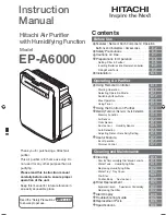
SPAN LENGTH t
*DEFLECTION
FORCE
h
C
d
H
D
*Apply force to the center of the span.
t = Span length, inches
C = Center distance, inches
D = Larger sheave diameter, inches
d = Smaller sheave diameter, inches
h = Deflection height, inches
DRIVE BELT TENSION ADJUSTMENT
MODEL
SHEAVE
DIAMETER
(in)
DEFLECTION
(in)
BELT
DRIVE
Used
New
15 Ton
B, BA
Standard
4.3 to 5.5
5.5 + .5
8.2 + .5
1/4 ± 1/16
20 Ton
B, BA
Standard
4.3 to 5.5
5.5 + .5
8.2 + .5
1/4 ± 1/16
DEFLECTION
FORCE (lbs)
TYPE
RECOMMENDED POUNDS OF FORCE PER BELT
When new V-belts are installed on a drive the initial tension will
drop rapidly during the first few hours. Check tension frequently
during the first 24 hours of operation. Subsequent retensioning
should fall between the minimum and maximum force. To deter-
mine the deflection distance from the normal position, use a
straightedge or stretch a cord from sheave to sheave to use as a
reference line. On multiple belt drives, an adjacent undeflected
belt can be used as a reference.
MOTOR SHEAVE ADJUSTMENTS
V
L
, V
M
& 2
VP
V
ARIABLE
P
ITCH
K
EY
T
YPE
M
OTOR
S
HEAVES
The driving and driven motor sheaves should be in alignment with
each other and the shafts parallel.
V
L
& V
M
S
HEAVES
A
DJUSTMENT
1. Loosen set screw “B” using a 5/32" Allen key.
2. Making half or full turns from closed position, adjust
sheave pitch diameter for desired speed. DO NOT OPEN
MORE THAN SIX FULL TURNS.
3. Tighten set screw “B” securely over flat.
4. Carefully put on belts and adjust belt tension. DO NOT
FORCE BELTS OVER GROOVES.
5. Ensure all keys are in place and the set screws tight before
starting drive. Recheck set screws and belt tension after
24 hours service.
NOTE: Future adjustments should be made by loosening the belt
tension and increasing or decreasing the pitch diameter of the
sheave by half or full turns as required. Readjust belt tension before
starting drive.
C
B
VL & VM
NOTE: Do not operate sheave with flange projecting beyond the
hub end.
GAS SYSTEM CHECK
Pre-Operation Checks
1. Close the manual gas valve external to the unit.
2. Turn off the electrical power supply to the unit.
3. Set the room thermostat to its lowest possible setting.
4. Remove the heat exchanger door on the side of the unit
by removing screws.
5. This unit is equipped with an ignition device which
automatically lights the main burner. DO NOT try to light
burner by any other method.
6. Move the gas control valve switch to the OFF position. Do
not force.
7. Wait five minutes to clear out any gas.
8. Smell for gas, including near the ground. This is important
because some types of gas are heavier than air. If you have
waited five minutes and you do smell gas, immediately
follow the warnings on page 3 of this manual. If having
waited for five minutes and no gas smell is noted, move
the gas control valve switch to the ON position.
9. Replace the heat exchanger door on the side of the unit.
10. Open the manual gas valve external to the unit.
11. Turn on the electrical power supply to the unit.
12. Set the thermostat to desired setting.
G
AS
S
UPPLY
P
RESSURES
& R
EGULATOR
A
DJUSTMENTS
S
HOULD
OVERHEATING
OCCUR
OR
THE
GAS
SUPPLY
FAIL
TO
SHUT
OFF
,
TURN
OFF
THE
MANUAL
GAS
SHUTOFF
VALVE
EXTERNAL
TO
THE
UNIT
BEFORE
TURNING
OFF
THE
ELECTRICAL
SUPPLY
.
WARNING
Содержание DCG Series
Страница 29: ...27 APPENDIX D WIRING DIAGRAMS...