


11
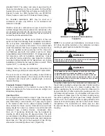
3. Locate 24” x ¼” tube in the bag assembly.
4. Install one end on front cover pressure switch.
5. Route tube to lower port on collector box cover and
cut off excess tubing.
Drain Trap and Lines
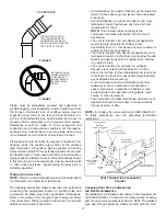
In horizontal applications the condensate drain trap is
secured to the furnace side panel, suspending it below the
furnace. A minimum clearance of 5.5” below the furnace must
be provided for the drain trap. Additionally, the appropriate
downward piping slope must be maintained from the drain
trap to the drain location. Refer to
Condensate Drain Trap
and Line
s for further details. If the drain trap and drain line
will be exposed to temperatures near or below freezing,
adequate measures must be taken to prevent condensate
from freezing.
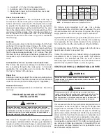
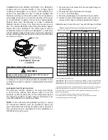
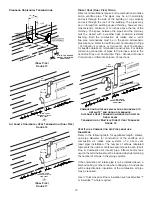
Leveling
Leveling ensures proper condensate drainage from the heat
exchanger. For proper flue pipe drainage, the furnace must
be level lengthwise from end to end. The furnace should have
a slight tilt from back to front with the access doors downhill
from the back panel approximately ½ to 3/4 inches. The slight
tilt allows the heat exchanger condensate, generated in the
recuperator coil, to flow forward to the recuperator coil front
cover.
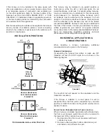
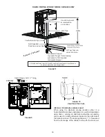
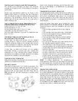
Alternate Electrical and Gas Line Connections
This furnace has provisions allowing for electrical and gas
line connections through either side panel. In horizontal
applications the connections can be made either through
the “top” or “bottom” of the furnace.
Drain Pan
A drain pan must be provided if the furnace is installed above
a conditioned area. The drain pan must cover the entire area
under the furnace (and air conditioning coil if applicable).
Freeze Protection
Refer to
Horizontal Applications and Conditions - Drain Trap
and Lines.
PROPANE GAS/HIGH ALTITUDE
INSTALLATIONS
WARNING
Possible Property damage, personal injury or death may
occur if the correct conversion kits are not installed. The
appropriate kits must be applied to ensure safe and proper
furnace operation. All conversions must be performed by a
qualified installer or service agency.
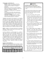
This furnace is shipped from the factory configured for
natural gas at standard altitude. Propane gas installations
require an orifice and spring change to compensate for the
energy content difference between natural and propane gas.
High
Stage
Low
Stage
Natural
None
#45
3.5" w.c.
1.9" w.c.
None
Propane
LPM-07*
1
1.25mm 10.0" w.c. 6.0" w.c.
None
Gas
Altitude
Kit
Orifice
Manifold Pressure
Pressure
Switch
Change
0-7000
1
LPM-07* supports both Honeywell and White-Rodgers 1-stage valves
NOTE:
In Canada, gas furnaces are only certified to 4500 feet.
For furnace being converted to LP gas, it is strongly
recommended that a LPLP03 kit also be installed. The use
of this kit will prevent the furnace from firing when the LP gas
supply pressure is too low to support proper combustion.
High altitude installations may require both a pressure switch
and an orifice/spring change. These changes are necessary
to compensate for the natural reduction in the density of
both the gas fuel and the combustion air at higher altitude.
For installations above 7000 feet, please refer to the furnace
Specification Sheets for required kit(s).
Contact the distributor for a tabular listing of appropriate
manufacturer’s kits for propane gas and/or high altitude
installations. The indicated kits must be used to insure
safe and proper furnace operation. All conversions must be
performed by a qualified installer, or service agency.
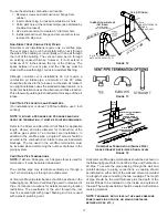
VENT/FLUE PIPE & COMBUSTION AIR PIPE
WARNING
Failure to follow these instructions can result in bodily
injury or death. Carefully read and follow all instructions
given in this section.
WARNING
Upon completion of the furnace installation, carefully
inspect the entire flue system both inside and outside of the
furnace to assure it is properly sealed. Leaks in the flue
system can result in serious personal injury or death due to
exposure to flue products, including carbon monoxide.
This manual will refer to the pipe that discharges products to
the outdoors as the “vent” pipe or “flue” pipe. The pipe that
supplies air for combustion to the furnace will be referred to
as the “intake” pipe or “combustion air” pipe. A condensing
gas furnace achieves its high level of efficiency by extracting
almost all of the heat from the products of combustion and
cooling them to the point where condensation takes place.
Because of the relatively low flue gas temperature and water
condensation requirements, PVC or ABS are typically used
as venting and intake pipe materials In Canada ABS is not
an approved vent pipe material, but it is permissible to use
as combustion air pipe material.
Содержание DC92SS
Страница 45: ...45 THIS PAGE IS LEFT INTENTIONALLY BLANK ...
Страница 46: ...46 THIS PAGE IS LEFT INTENTIONALLY BLANK ...
Страница 47: ...47 THIS PAGE IS LEFT INTENTIONALLY BLANK ...


