Installation manual
2
BRC1D528
Remote controller
4PW23716-1
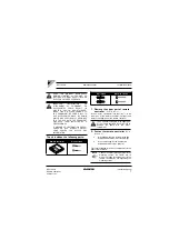
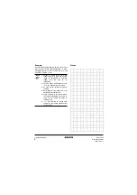
3. Wire the indoor unit
Connect the terminals on top of the upper part of the
remote controller (P1, P2), and the terminals of the
indoor unit (P1, P2). (P1 and P2 do not have polarity.)
Wiring specifications
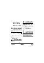
4. Reattach the upper part of the
remote controller
Refer to
First begin fitting from the clips at the bottom.
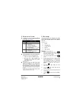
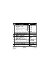
If controlling one indoor unit or one
group of indoor units with two remote
controllers
Change the MAIN/SUB changeover switch setting as
described below
Set one remote controller to “main”, and the other to
“sub”.
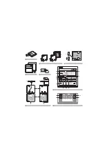
1
indoor unit
2
lower part of the remote controller
3
upper part of the remote controller
4
wired from the rear
5
wired from the top
6
notch the part for the wiring to pass through
with nippers, etc.
NOTE
When wiring, run the wiring away from
the power supply wiring in order to avoid
receiving electric noise (external noise).
Wiring type
Size
2 wire
0.75–1.25 mm
2
NOTE
Peel the shield for the part that has to
pass through the inside of the remote
controller case (
l
). Refer to
Be careful not to pinch the wiring when
attaching.
NOTE
1.
The switch box and wiring for
connection are not included.
2.
Do not directly touch the PC board
with your hand.
1
Main remote controller (factory set)
2
Sub remote controller
NOTE
1.
If controlling with one remote controller,
be sure to set it to “main”.
2.
Set the remote controller before turning
the power supply on.
“
88
” is displayed for about one minute when the
power supply is turned on. During this time the
remote controller can not be operated.
Содержание BRC1D528
Страница 1: ...Remote controller BRC1D528 INSTALLATION MANUAL...
Страница 9: ...NOTES...
Страница 10: ...Zandvoordestraat 300 B 8400 Oostende Belgium 4PW23716 1...


