background image

English

1

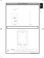
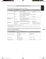
All dimensions are in mm

Dimension 

Model

A

B

C

D

E

F

G

H

I

J

K

BAG

33.5 118.4 183.4 33.5

46

.0

154

.0

1.5

43

.0

114

.0

1.5

1

79

.0

OUTLINE AND DIMENSIONS

Original Instruction

TOP VIEW

SIDE VIEW

FRONT VIEW

1 IM-5WMYJ-0113(2)DAIKIN_EN.indd1  1

1 IM-5WMYJ-0113(2)DAIKIN_EN.indd1 1

6/10/14  10:07:23 AM

6/10/14 10:07:23 AM

A

B

C

D

E

F

G

H

I

J

K

Содержание BAG

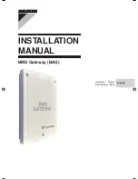
Страница 1: ...INSTALLATION MANUAL BMS Gateway BAG Installation Manual BMS Gateway BAG English ...

Страница 2: ...dimensions are in mm Dimension Model A B C D E F G H I J K BAG 33 5 118 4 183 4 33 5 46 0 154 0 1 5 43 0 114 0 1 5 179 0 OUTLINE AND DIMENSIONS Original Instruction TOP VIEW SIDE VIEW FRONT VIEW A B C D E F G H I J K ...

Страница 3: ...form as a result of excessive heat or chemical reaction Don t use joined and twisted wires for incoming power supply The equipment is not intended for use in a potentially explosive atmosphere SAFETY PRECAUTIONS INSTALLATION MANUAL This manual provides the procedures of installation to ensure a safe and good standard of operation for the BMS Access Gateway Special adjustment may be necessary to su...

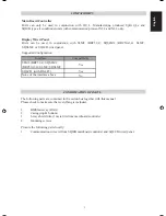
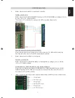
Страница 4: ...l CONFIRMATION OF PARTS The following parts are contained in the carton box together with this manual Please check to make sure that everything is included 1 BMS Gateway BAG 2 Casing top bottom 3 5 way shield wire 1 meter to from mainboard controller 4 Mounting screws Procure the following parts locally 1 Communication wires to from SQMB mainboard controller and SQLCD wired panel Compatibility Int...

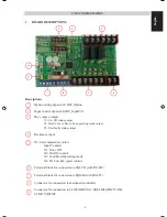
Страница 5: ...rating mode output Y3 Unit faulty status output Resistance input X5 Set temperature control Input Contacts X1 Force Off X2 On Off control X3 Cool Heat Operating mode X4 Hi Low Fan speed control Terminal block for connection to SQLCD with RS 485 Terminal block for connection to SQMB with RS 485 Connector for connection to mainboard controller Connector for connection to SLM8 BRC51A SQSLM8 BRC51A64 ...

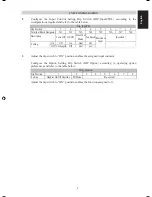
Страница 6: ...ned to it UNIT CONFIGURATION Configure the Input Control Setting Dip Switch DIP_InputCTRL according to the configurations required and refer to the table below Dip_InputCtrl Dip Position Force Off On Off Heat Cool Mode Hi Fan Speed Resistance Input Reserved 2 3 4 5 6 7 8 X1 X3 X2 X4 X5 X6 X7 Low Dip_Option Dip Position Setting Handset On Off Override SQ Mode Reserved Terminal Block Designator Desc...

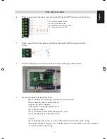
Страница 7: ...end of the wire to CN_WIR on mainboard controller 2 Make connections from BAG to wired panel SQLCD with RS 485 Make connections from TB_WIR BAG to TB SQLCD accordingly A to A B to B 5V to 5V GND to GND SLM8 BRC51A SQSLM8 BRC51A64 SLM9 SQSLM9 Plug in the wire harness provided in SLM8 BRC51A SQSLM8 BRC51A64 SLM9 SQSLM9 package to CN_MB on wired panel and connects the other end of the wire to the con...

Страница 8: ...tions in your decision Do not install the unit in location that is Exposed to direct sunlight Susceptible to humidity and moisture Near to heat source Near to machines that emits high frequency wave Near to high current switching devices Caution Over tightening the screws can cause deformation or and crack at the casing Mount the bottom casing on a wall with flat surface Unit mounted on an uneven ...

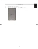
Страница 9: ...8 English UNIT INSTALLATION 8 Mount the complete unit onto the wall 9 Close the top casing to the bottom casing and tighten the screws ...

Страница 10: ... 2 DAIKIN_EN indd11 11 6 10 14 10 07 25 AM English BAG to mainboard controller BAG to BMS The maximum wire length for IO communication type between BAG Wired Panel and BAG mainboard controller shall not exceed 30 meters ...

Страница 11: ...English OPERATING INSTALLATION MANUAL BMS Gateway BAG Operating Installation Manual BMS Gateway BAG ...

Страница 12: ...OPERATING MANUAL English BMS Gateway BAG Operating Manual BMS Gateway BAG ...

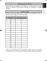
Страница 13: ...m to control the set temperature of the air conditioner unit according to resistance table below BMS Access Gateway BAG Resistance Input The accuracy of Resistance to Set Temperature conversion is subject to the stability of the input voltage 12V from the main controller and may differ at site application Resistance Set Temperature C 18 19 20 21 22 23 24 25 26 27 28 30 16 17 29 140 200 260 320 380...

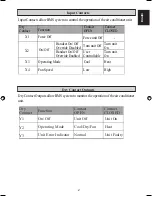
Страница 14: ...uts X1 X2 X3 X4 Force Off On Off Operating Mode Fan Speed Handset On Off Override Disabled Handset On Off Override Enabled Force unit Off Turn unit Off User Controllable Cool Low Turn unit On Turn unit On Heat High Dry Contact Function Contact OPEN Contact CLOSED Y1 Y2 Y3 Dry Contact Function Contact Contact CLOSED Unit On Heat Unit Faulty Operating Mode Unit Error Indicator On Off OPEN Unit Off C...

Страница 15: ...MEMO ENGLISH ...
Отзывы: