Daikin ARXM50N2V1B Скачать руководство пользователя страница 14

6 Installation

Installer reference guide

14

RXF50+60B2_RXF71A2_RXP50~71L2_(A)RXM42~71N2_RXJ50N2_

RXA42+50B2

R32 split series

4P513661-6B – 2018.05
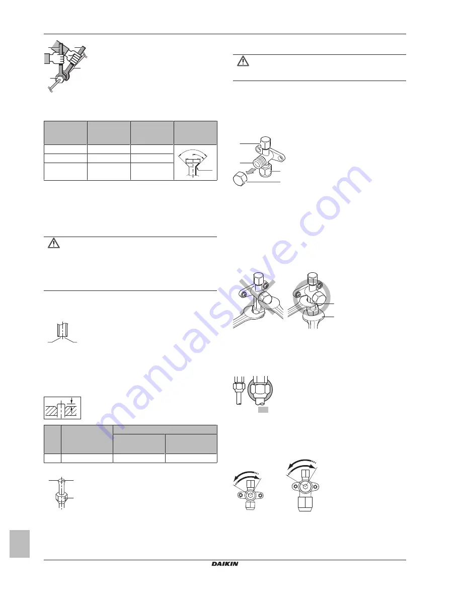
a

b

c

d

a

Torque wrench

b

Spanner

c

Piping union

d

Flare nut

Piping size

(mm)

Tightening

torque (N•m)

Flare

dimensions (A)

(mm)

Flare shape

(mm)

Ø6.4

15~17

8.7~9.1

R=0.4~0.8

45° ±2

90°±2

A

Ø12.7

50~60

16.2~16.6

Ø15.9

63~75

19.3~19.7

6.4.4

Pipe bending guidelines

Use  a  pipe  bender  for  bending.  All  pipe  bends  should  be  as  gentle
as possible (bending radius should be 30~40 mm or larger).

6.4.5

To flare the pipe end

CAUTION

▪ Incomplete flaring may cause refrigerant gas leakage.

▪ Do  NOT  re-use  flares.  Use  new  flares  to  prevent

refrigerant gas leakage.

▪ Use  flare  nuts  that  are  included  with  the  unit.  Using

different flare nuts may cause refrigerant gas leakage.

1

Cut the pipe end with a pipe cutter.

2

Remove  burrs  with  the  cut  surface  facing  down  so  that  the
chips do NOT enter the pipe.

a

b

a

Cut exactly at right angles.

b

Remove burrs.

3

Remove  the  flare  nut  from  the  stop  valve  and  put  the  flare  nut
on the pipe.

4

Flare  the  pipe.  Set  exactly  at  the  position  as  shown  in  the
following figure.

A

Flare tool for R32

(clutch type)

Conventional flare tool

Clutch type

(Ridgid-type)

Wing nut type

(Imperial-type)

A

0~0.5 mm

1.0~1.5 mm

1.5~2.0 mm

5

Check that the flaring is properly made.

a

b

c

a

Flare’s inner surface MUST be flawless.

b

The pipe end MUST be evenly flared in a perfect circle.

c

Make sure the flare nut is fitted.

6.4.6

Using the stop valve and service port

CAUTION

Do  NOT  open  the  valves  before  flaring  is  complete.  This
would cause refrigerant gas leakage.

To handle the stop valve

Take the following guidelines into account:

▪ The stop valves are factory closed.

▪ The  following  figure  shows  the  stop  valve  parts  required  when

handling the valve.

c
d

a

b

a

Service port and service port cap

b

Valve stem

c

Field piping connection

d

Stem cap

▪ Keep both stop valves open during operation.

▪ Do  NOT  apply  excessive  force  to  the  valve  stem.  Doing  so  may

break the valve body.

▪ ALWAYS make sure to secure the stop valve with a spanner, then

loosen or tighten the flare nut with a torque wrench. Do NOT place
the  spanner  on  the  stem  cap,  as  this  could  cause  a  refrigerant
leak.

a

b

a

Spanner

b

Torque wrench

▪ When  it  is  expected  that  the  operating  pressure  will  be  low  (e.g.

when  cooling  will  be  performed  while  the  outside  air  temperature
is  low),  sufficiently  seal  the  flare  nut  in  the  stop  valve  on  the  gas
line with silicon sealant to prevent freezing.

Silicon sealant; make sure there is no gap.

To open/close the stop valve

1

Remove the stop valve cover.

2

Insert  a  hexagon  wrench  (liquid  side:  4  mm,  gas  side:  4  mm)
into the valve stem and turn the valve stem:

Counterclockwise to open.
Clockwise to close.

3

When  the  stop  valve  CANNOT  be  turned  any  further,  stop
turning. The valve is now open/closed.

Содержание ARXM50N2V1B

Страница 1: ...de R32 split series English Installer reference guide R32 split series RXF50B2V1B RXF60B2V1B RXF71A2V1B RXP50L2V1B RXP60L2V1B RXP71L2V1B ARXM50N2V1B RXM42N2V1B RXM50N2V1B RXM60N2V1B RXM71N2V1B RXJ50N2V1B RXA42B2V1B RXA50B2V1B ...

Страница 2: ... refrigerant piping 15 6 5 3 To check for leaks 15 6 5 4 To perform vacuum drying 15 6 6 Charging refrigerant 16 6 6 1 About charging refrigerant 16 6 6 2 About the refrigerant 16 6 6 3 Precautions when charging refrigerant 17 6 6 4 To determine the additional refrigerant amount 17 6 6 5 To determine the complete recharge amount 17 6 6 6 To charge additional refrigerant 17 6 6 7 To fix the fluorin...

Страница 3: ...e accessories optional equipment and spare parts made or approved by Daikin WARNING Make sure installation testing and applied materials comply with applicable legislation on top of the instructions described in the Daikin documentation CAUTION Wear adequate personal protective equipment protective gloves safety glasses when installing maintaining or servicing the system WARNING Tear apart and thr...

Страница 4: ...islation for example national gas regulation and are executed only by authorised persons Installation space requirements NOTICE Pipework shall be protected from physical damage Installation of pipework shall be kept to a minimum WARNING If appliances contain R32 refrigerant the floor area of the room in which the appliances are installed operated and stored MUST be larger than the minimum floor ar...

Страница 5: ...rant gas leaks ventilate the area immediately Possible risks Excessive refrigerant concentrations in a closed room can lead to oxygen deficiency Toxic gas may be produced if refrigerant gas comes into contact with fire DANGER RISK OF EXPLOSION Pump down Refrigerant leakage If you want to pump down the system and there is a leak in the refrigerant circuit Do NOT use the unit s automatic pump down f...

Страница 6: ...under overvoltage category III condition MUST be installed in the fixed wiring WARNING ONLY use copper wires Make sure the field wiring complies with the applicable legislation All field wiring MUST be performed in accordance with the wiring diagram supplied with the product NEVER squeeze bundled cables and make sure they do NOT come in contact with the piping and sharp edges Make sure no external...

Страница 7: ...ore installing About the documentation What documentation exists for the installer About the box How to unpack the units and remove their accessories About the unit How to identify the unit Preparation What to do and know before going on site Installation What to do and know to install the system Configuration What to do and know to configure the system after it is installed Commissioning What to ...

Страница 8: ...nit is mildly flammable 4 1 Overview About the unit This chapter contains information about Identification of the outdoor unit 4 2 Identification NOTICE When installing or servicing several units at the same time make sure NOT to switch the service panels between different models 4 2 1 Identification label Outdoor unit Location 5 Preparation 5 1 Overview Preparation This chapter describes what you...

Страница 9: ... a Air outlet b Air inlet NOTICE The height of the wall on the outlet side of the outdoor unit MUST be 1200 mm NOTICE Do NOT stack the units on each other Do NOT hang the unit on a ceiling Strong winds 18 km h blowing against the outdoor unit s air outlet causes short circuit suction of discharge air This may result in deterioration of the operational capacity frequent frost acceleration in heatin...

Страница 10: ...he heat exchanger coil is NOT affected by the snow If necessary install a snow cover or shed and a pedestal 5 3 Preparing refrigerant piping 5 3 1 Refrigerant piping requirements INFORMATION Also read the precautions and requirements in the General safety precautions chapter Piping material Phosphoric acid deoxidised seamless copper Piping diameter Class 42 60 Class 71 Liquid piping Ø6 4 mm 1 4 Ga...

Страница 11: ...nstallation 6 1 Overview Installation This chapter describes what you have to do and know on site to install the system Typical workflow Installation typically consists of the following stages 1 Opening the units 2 Mounting the outdoor unit 3 Connecting the refrigerant piping 4 Checking the refrigerant piping 5 Charging refrigerant 6 Connecting the electrical wiring 7 Finishing the outdoor unit in...

Страница 12: ...tall the unit on a frame install a waterproof plate within 150 mm of the bottom side of the unit in order to prevent water from getting into the unit and to avoid drain water dripping see the following figure NOTICE If the unit is installed in a cold climate take adequate measures so that the evacuated condensate CANNOT freeze INFORMATION For information on the available options contact your deale...

Страница 13: ... piping into account Avoid anything but the designated refrigerant to get mixed into the refrigerant cycle e g air Only use R32 when adding refrigerant Only use installation tools e g manifold gauge set that are exclusively used for R32 installations to withstand the pressure and to prevent foreign materials e g mineral oils and moisture from mixing into the system Install the piping so that the f...

Страница 14: ...ade a b c a Flare s inner surface MUST be flawless b The pipe end MUST be evenly flared in a perfect circle c Make sure the flare nut is fitted 6 4 6 Using the stop valve and service port CAUTION Do NOT open the valves before flaring is complete This would cause refrigerant gas leakage To handle the stop valve Take the following guidelines into account The stop valves are factory closed The follow...

Страница 15: ...of the following stages 1 Checking for leaks in the refrigerant piping 2 Performing vacuum drying to remove all moisture air or nitrogen from the refrigerant piping If there is a possibility of moisture being present in the refrigerant piping for example water may have entered the piping first carry out the vacuum drying procedure below until all moisture has been removed 6 5 2 Precautions when ch...

Страница 16: ...ngth is more than specified see later Completely recharging refrigerant Example When relocating the system After a leak Charging additional refrigerant Before charging additional refrigerant make sure the outdoor unit s external refrigerant piping is checked leak test vacuum drying INFORMATION Depending on the units and or the installation conditions it might be necessary to connect electrical wir...

Страница 17: ...tective gloves and safety glasses CAUTION To avoid compressor breakdown do NOT charge more than the specified amount of refrigerant Prerequisite Before charging refrigerant make sure the refrigerant piping is connected and checked leak test and vacuum drying 1 Connect the refrigerant cylinder to the service port 2 Charge the additional refrigerant amount 3 Open the gas stop valve If pump down is n...

Страница 18: ...ds DANGER RISK OF ELECTROCUTION Disconnect the power supply for more than 10 minutes and measure the voltage at the terminals of main circuit capacitors or electrical components before servicing The voltage MUST be less than 50 V DC before you can touch electrical components For the location of the terminals see the wiring diagram b c DC P1 DC N1 a d e g f a Multimeter DC voltage range b S80 rever...

Страница 19: ...pen the wire clamp 4 Connect the interconnection cable and power supply as follows 50 Hz 220 240 V c d f a b e a Interconnection cable b Power supply cable c Field fuse d Earth leakage circuit breaker e Power supply f Earth 1 2 3 3 5 Tighten the terminal screws securely We recommend using a Phillips screwdriver 6 Install the switch box cover 6 8 Finishing the outdoor unit installation 6 8 1 To fin...

Страница 20: ...est speed Do NOT use this setting in residences or offices with people 7 2 Standby electricity saving function 7 2 1 About the standby electricity saving function This mode turns OFF the power supply of the outdoor unit and sets the indoor unit into the standby saving mode to reduce the power consumption of the unit This mode is only applicable for outdoor units RXM50 60N and indoor units FTXM INF...

Страница 21: ...missioning To perform an air purge To perform a test run 8 5 To perform a test run Prerequisite Power supply MUST be in the specified range Prerequisite Test run may be performed in cooling or heating mode Prerequisite Test run should be performed in accordance with the operation manual of the indoor unit to make sure that all functions and parts are working properly 1 In cooling mode select the l...

Страница 22: ...ed from the mains Turn off the respective circuit breaker When a safety device was activated stop the unit and find out why the safety device was activated before resetting it NEVER shunt safety devices or change their values to a value other than the factory default setting If you are unable to find the cause of the problem call your dealer DANGER RISK OF ELECTROCUTION WARNING Prevent hazards due...

Страница 23: ...stop the compressor before removing the refrigerant piping If the compressor is still running and the stop valve is open during pump down air will be sucked into the system Compressor breakdown or damage to the system can result due to abnormal pressure in the refrigerant cycle Pump down operation will extract all refrigerant from the system into the outdoor unit 1 Remove the valve cap from the li...

Страница 24: ...OR HR MR _A MR _B S U V W X A K R_ D V D DIODE DB DIODE BRIDGE DS DIP SWITCH E H HEATER F U FU FOR CHARACTERISTICS FUSE REFER TO PCB INSIDE YOUR UNIT FG CONNECTOR FRAME GROUND H HARNESS H P LED V L PILOT LAMP LIGHT EMITTING DIODE HAP LIGHT EMITTING DIODE SERVICE MONITOR GREEN HIGH VOLTAGE HIGH VOLTAGE IES INTELLIGENT EYE SENSOR IPM INTELLIGENT POWER MODULE K R KCR KFR KHuR K M MAGNETIC RELAY L LIV...

Страница 25: ...utdoor temperature Thermistor Refrigerant flow Cooling Heating PED categories of equipment High pressure switch category IV Compressor category II Other equipment art 4 3 Applicable for RXP60L RXP71L RXF60B RXF71A M HPS High pressure switch Automatic reset Heat exchanger 7 0 CuT 7 0 CuT 7 0 CuT 7 0 CuT 7 0 CuT 7 0 CuT 12 7 CuT 12 7 CuT 12 7 CuT 12 7 CuT 12 7 CuT 12 7 CuT 9 5 CuT 6 4 CuT 9 5 CuT 6 ...

Страница 26: ...ipment High pressure switch category IV Compressor category II Other equipment art 4 3 Applicable for RXM42N RXM50N RXM60N ARXM50N RXJ50N RXA42B RXA50B M HPS High pressure switch Automatic reset Heat exchanger 7 0 CuT 7 0 CuT 7 0 CuT 7 0 CuT 7 0 CuT 7 0 CuT 12 7 CuT 12 7 CuT 12 7 CuT 12 7 CuT 12 7 CuT 12 7 CuT 6 4 CuT 9 5 CuT 6 4 CuT 6 4 CuT 6 4 CuT 6 4 CuT 4 0 CuT 4 0 CuT 4 0 CuT 9 5 CuT 9 5 CuT ...

Страница 27: ...nd maintain it Operation manual Instruction manual specified for a certain product or application explaining how to operate it Maintenance instructions Instruction manual specified for a certain product or application which explains if relevant how to install configure operate and or maintain the product or application Accessories Labels manuals information sheets and equipment that are delivered ...

Страница 28: ...4P513661 6B 2018 05 Copyright 2018 Daikin ...

Отзывы: