Si12-994
Removal of PCBs (Pattern 1)
Removal Procedure
13
5
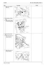
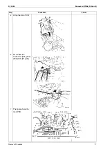
Remove the drip proof
plate.
6
Disconnect the
connectors [S52]
[S102] from the service
monitor PCB.
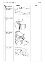
7
The figure shows the
service monitor PCB.
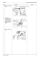
8
Release the 2 hooks to
remove the service
monitor PCB.
Step
Procedure
Points
(R6577)
Drip proof plate
(R6578)
[S102]
[S52]
Service
monitor PCB
Priority room setting switch
(SW4)
Wiring error check switch
(SW3)
Forced operation ON / OFF
switch (SW1)
NIGHT QUIET mode setting
switch (SW5)
Operation mode switch
(SW2)
LED A
LED 1
LED 2
LED 3
LED 4
(R3064)
(R6579)
Hook
Hook

