3 About the box
Installation manual
5
ETVH/9W
Daikin Altherma 3 H HT F
4P644728-1 – 2021.02
30])
WARNING
Commissioning method MUST be in accordance with the
instructions
from
this
manual.
See
3
About the box
3.1
Indoor unit
3.1.1
To remove the accessories from the
indoor unit
1×
b
4×
a
1×
c
1×
d
1×
e
1×
f
4×
i
6×
h
1×
j
1×
g
a
Shut-off valves for water circuit
b
Overpressure bypass valve
c
General safety precautions
d
Addendum book for optional equipment
e
Indoor unit installation manual
f
Operation manual
g
WLAN cartridge
h
Sealing rings for shut-off valves (space heating water
circuit)
i
Sealing rings for field-supplied shut-off valves (domestic
hot water circuit)
j
Sealing tape for low voltage wiring intake
3.1.2
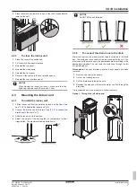
To handle the indoor unit
Use the handles at the back and at the bottom to carry the unit.
b
a
a
b
a
Handles at the back of the unit
b
Handles at the bottom of the unit. Carefully tilt the unit to
the back so that the handles become visible.
4
Unit installation
4.1
Preparing the installation site
4.1.1
Installation site requirements of the
indoor unit
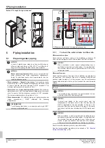
▪ The indoor unit is designed for indoor installation only and for the
following ambient temperatures:
▪ Space heating operation: 5~30°C
▪ Space cooling operation: 5~35°C
▪ Domestic hot water production: 5~35°C
INFORMATION
Cooling is only applicable in case of:
▪ Reversible models
▪ Heating only conversion kit (EKHVCONV*)
▪ Mind the measurement guidelines:
Maximum height difference between indoor unit and
outdoor unit
10 m
Maximum total water piping length
50 m
(a)
(a)
Precise water piping length can be determined using the Hydronic
Piping Calculation tool. The Hydronic Piping Calculation tool is
part of the Heating Solutions Navigator which can be reached via
https://professional.standbyme.daikin.eu
. Please contact your
dealer if you have no access to Heating Solutions Navigator.
▪ Mind the following spacing installation guidelines:
≥300
≥600
≥500
(mm)
INFORMATION
If you have limited installation space, do the following
before installing the unit in its final position:
connect the drain hose to the drain"
7]. It requires to
remove one or both side panels.
4.2
Opening and closing the unit
4.2.1
To open the indoor unit
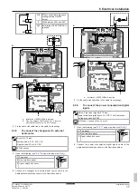
Overview
a
b
d
c e
a
Top panel
b
User interface panel
c
Switch box cover
d
Front panel
e
High voltage switch box cover
Open
1
Remove the top panel.
Содержание 3 H HT F
Страница 37: ......
Страница 38: ......
Страница 39: ......
Страница 40: ...4P644728 1 2021 02 Copyright 2021 Daikin 4P644728 1 0000000T Verantwortung f r Energie und Umwelt...


