


IM 1167
33
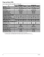
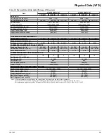
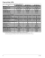
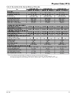
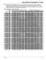
Physical Data (VFD)
Table 28: Physical Data (60 Hz, High Efficiency, VFD models)
CIRCUIT 1
CIRCUIT 2
CIRCUIT 1
CIRCUIT 2
CIRCUIT 1
CIRCUIT 2
Unit Cap. @ AHRI tons (kW)
Unit Operating Charge lbs (kg)
265 (120)
265 (120)
270 (122)
320 (145)
320 (145)
320 (145)
Unit Dimensions
L x W x H, in. (mm)
Unit Operating Weight, lbs. (kg)
Unit Shipping Weight, lbs (kg)
Weight-Add for Copper Fins
Weight-Add for Louvered Panels
Nominal Capacity, tons (kW)
175 (615)
175 (615)
175 (615)
205 (721)
205 (721)
205 (721)
Minimum Capacity (% of Full Load)
Oil charge per circuit , gallons (liters)
6 (23)
6 (23)
6 (23)
6 (23)
6 (23)
6 (23)
Pumpdown Capacity, lbs (kg)
416 (189)
416 (189)
416 (189)
500 (227)
500 (227)
500 (227)
Coil Inlet Face Area, sq. ft. (sq. m.)
246.1 (22.8)
246.1 (22.8)
246.1 (22.8)
295.3 (27.4)
295.3 (27.4)
295.3 (27.4)
Rows Deep/Fins Per Inch
3 / 16
3 / 16
3 / 16
3 / 16
3 / 16
3 / 16
Number of Fans per Circuit
Fan Diameter: 31.5 in. (800 mm)
Fan Motor, hp (kW)
Fan & Motor RPM
Fan Tip Speed, fpm (m/s)
Airflow, cfm (l/s)
Shell Dia.-Tube Length, in.(mm)
Water Volume, gallons (liters)
Victaulic inlet/outlet conn. in. (mm)
Max. Water Pressure, psi (kPa)
Max. Refrigerant Press., psi (kPa)
325 (2241)
325 (2241)
325 (2241)
152 (1048)
152 (1048)
152 (1048)
8 (219)
8 (219)
8 (219)
6984 (35)
20 x 108 / (508 x 2750)
20 x 108 / (508 x 2750)
20 x 108 / (508 x 2750)
EVAPORATOR, DIRECT EXPANSION SHELL AND TUBE
221700 (104630)
243870 (115094)
266040 (125556)
6984 (35)
6984 (35)
1.4 (1.05)
1.4 (1.05)
850
850
1.4 (1.05)
850
COMPRESSORS, SCREW, SEMI-HERMETIC
20
20
20
1236 (561)
1348 (611)
1460 (662)
2968 (1346)
3256 (1477)
3553 (1612)
AWS350BDH VFD
20729 (9403)
22033 (9994)
22838 (10359)
21596 (9796)
22900 (10387)
23705 (10753)
BASIC DATA
Data
10402 x 2225 x 2545
11701 x 2225 x 2548
12604 x 2225 x 2545
AWS390BDH VFD
AWS410BDH VFD
347.1 (1220)
377.8 (1328)
408.7 (1437)
410 x 88 x 100
461 x 88 x 100
496 x 88 x 100
10
12
12
12
102 (386)
CONDENSERS, HIGH EFFICIENCY FIN AND TUBE TYPE
100 (377)
100 (377)
CONDENSER FANS, DIRECT DRIVE PROPELLER TYPE
10
10
Note: A 20 mesh strainer must be placed in the supply water line just prior to the inlet of the evaporator.
Care must be exercised when welding pipe or flanges to the evaporator to prevent any slag from entering the vessel.
This information applies only to Rev 0B models of AWS-B. For Rev 00 models, consult CAT 600-6; Rev 0A, CAT 600-7.
Содержание AWS210BDS
Страница 65: ...IM 1167 65 Wiring Diagram Wiring Diagram Figure 41 Field Wiring Diagram...
Страница 66: ...66 IM1167 Wiring Diagram Figure 42 Field Wiring Diagram continued...
Страница 215: ......