1.1 General Description of Interface Panel Function
1-2
Item
Specification
Editing method
Recorded with teach pendant
Editing also possible on a personal computer using commercially available
text editor
Display method
Single-action touch ON/OFF display operation using dedicated key
Display also possible with input signals
1.1.3 Signal attributes
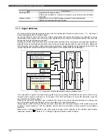
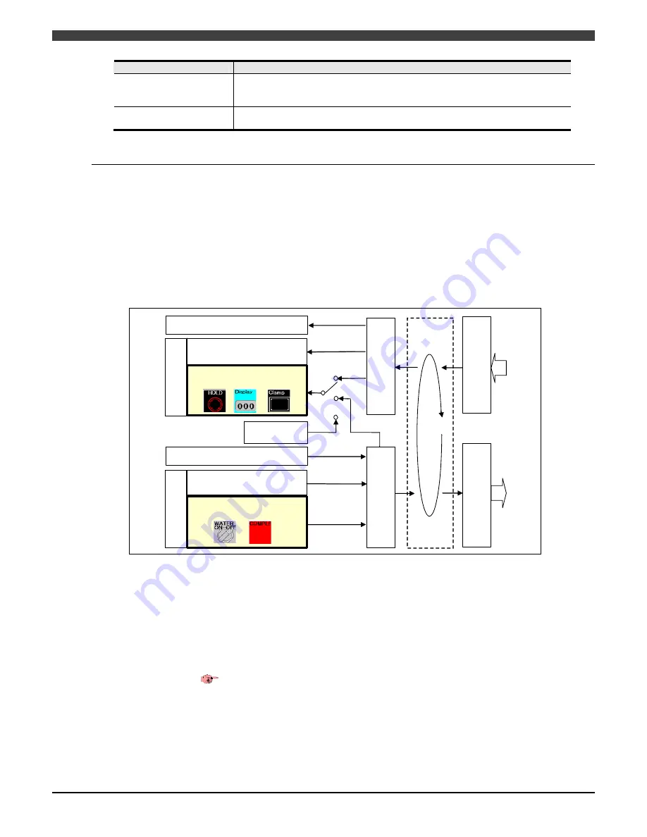
An overview of the input/output signals involved with the interface panel function is shown in Fig. 1.1.2 Overview of
input/output signals used by interface panel.
As with the "starting," "servo ON" and other status output signals, the logical output signals are allocated for use as
the interface panel outputs, that is to say, as the signals which are output to the external device when the push
buttons and selector switches are operated.
Similarly, as with the "start" instruction, "servo ON" instruction and other status input signals, the logical input signals are
allocated for use as the interface panel inputs, that is to say, as the input signals which are used for the lamp, display and
other indications, and in addition, logical output signals and internal control variables can be displayed as well. (Not only
the input signals from external sources but the output signals of the controller itself can be displayed.)
Internal control
variables
Interface panel outputs
Push buttons, selector switches, etc.
Interface panel inputs
Lamps, displays, etc.
"Start" instruction, "servo ON" instruction
and other status output signals
General-purpose output signals
General-purpose input signals
"Start" instruction, "servo ON" instruction
and other status input signals
2048 logical
i
nput signals
Software
PLC
2048 logical output signals
2048 external input si
gnals
2048 external output signals
S
tatus input signals
S
tatus output signals
Individually
set
Fig. 1.1.2 Overview of input/output signals used by interface panel
It is not possible to operate the logical input signals directly by operating the interface panel outputs, that is to say,
the push buttons, selector switches, etc. on the panel. (The "start" instruction and "servo ON" instruction cannot be
executed from the interface panel.)
However, as is shown in the figure, when a software PLC is used, the fore-mentioned restrictions do not apply, and
any of the interface panel input/outputs can be connected to any input/output signals.
Output signals, which have been already allocated, cannot be set to the output signals of the interface panel. By
contraries, output signals set with the interface panel cannot be allocated as output signals having different
functions.
Signal which is already allocated to the other purpose usage can be allocated to the interface panel display
(duplicate allocation).
Refer to “2.1.5 Setting of signals duplication check” for detail.


