background image

5. Inspection of dashpot

(For automatic transmission-equipped model only)
Preparation to be made prior to idle speed adjustment

· 

Check and adjust the ignition timing.

· 

Check and adjust the idle speed.

· 

Apply the parking brake fully.

· 

Warm up the engine thoroughly.

· 

All accessory switches are turned OFF.
(On those vehicles equipped with a day-light system, set the light control switch to the first stage, in
order to turn OFF the head lights.)

· 

The air element is installed.

· 

All vacuum hoses are connected properly.

· 

Ensure that the intake system exhibits no gas leakage or air admission.

· 

Ensure that there is no gas leakage.

· 

Place the shift lever in the “N” or “P” range.

· 

Place the steering wheel to the straight ahead position and do not operate it during the inspection.

MA–22

(1) Connection of tachometer

(Refer to the “Inspection and adjustment of ignition timing” section for the connection of tachome-
ter.)

CAUTION :

· 

Never allow the tachometer terminal to touch ground. It could result in damage of the ignition system.

· 

As some tachometers are not compatible with this ignition system, it is recommended to confirm the
compatibility with your unit before its use.

(2) Start and warm up the engine.
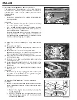
(3) Ensure that the adjusting screw of the dashpot is not in contact with the dashpot shaft when the en-

gine revolution is held at about 2400 

±

100 rpm.

If the adjusting screw of the dashpot is in contact with the dashpot shaft, adjust the height of the ad-
justing screw.

(4) Ensure that the duration of time from dash pot adjusting screw contacts to the dash pot shaft to en-

gine revolution returns to idle speed is within specified value when the throttle lever released slowly
from the engine revolution at 3500 rpm.

Specified Duration: 0.5 - 5.0 seconds.

If the measured duration of time fails to meet with the specified value, replace the dashpot with a
new one.
(Refer to the EC section.)

JMA00062-00000

JMA00063-00000

Содержание TERIOS J100

Страница 1: ...SE TUBE MA 28 FRONT BRAKE MA 29 REAR BRAKE MA 32 BRAKE BOOSTER HOSE MA 34 BRAKE MASTER CYLINDER MA 35 MUFFLER AND EXHAUST PIPE MA 37 AUTOMATIC TRANSMISSION MA 37 CLUTCH MA 38 MANUAL TRANSMISSION TRANS...

Страница 2: ...cting the periodical maintenance service only is insuffi cient It is essential that owners themselves perform maintenance such as the pre starting check de scribed in the owner s manual so that the ve...

Страница 3: ...42 48 54 60 0 5 1 1 5 2 2 5 3 3 5 4 4 5 5 1000 miles Years Cleaning Check Damage Engine Exhaust emission control system Air cleaner element Valve clearance Check adjustment MA 6 MA 18 Engine oil oil...

Страница 4: ...scratch cut twist and swelling Automatic transmission Oil cooler hose MA 38 Change Oil Transfer MA 39 Change Oil Differential Front Rear MA 39 Check Tightness Rattle Damage Propeller shaft MA 40 Check...

Страница 5: ...or inspect Change or replace Section Item What to do Inspection interval See page 1000 km 1 10 20 30 40 50 60 70 80 90 100 0 6 6 12 18 24 30 36 42 48 54 60 0 5 1 1 5 2 2 5 3 3 5 4 4 5 5 1000 miles Yea...

Страница 6: ...lt Alternator and water pump 5 6 mm Vane pump Power steering 11 14 mm If necessary adjust the drive belt tension Refer to the EM or SR section 2 Inspection of air filter element 1 Removal of air filte...

Страница 7: ...ge as necessary 2 Remove the oil filler cap 3 Disconnect the blow by gas hose from the throttle body 4 Ensure that no resistance exists when you blow your breath to the disconnected hose end which was...

Страница 8: ...termi nals in the fuel pump relay connector may cause fuel pump malfunction or other serious malfunctions due to lowered insulation of each terminal MA 8 6 Connect the No 1 and No 2 terminals of the f...

Страница 9: ...eplacement of fuel filter WARNING Never smoke or work near open flame Failure to observe this warning will cause fire Removal 1 Ensure that the ignition switch is turned OFF 2 Open the fuel filler cap...

Страница 10: ...faces to fuel pump side Failure to observe this caution may lead to fuel filter malfunction 2 Insert new hose clips to the fuel hoses 3 Connect the fuel hoses to the fuel filter until the fuel hose en...

Страница 11: ...le body side A and atmosphere side C pipes plugged If air leakage exceeding the above specified value is present replace the charcoal canister with a new one e Ensure that no air continuity exists whe...

Страница 12: ...ion is given in this installation procedure q Install the charcoal canister to the charcoal canis ter holder and lock it securely w Connect the atmosphere side hose to the charcoal canister e Install...

Страница 13: ...hand 11 Wipe off the engine oil from the oil filter attaching part of the engine oil filter bracket 12 Thinly apply engine oil to the O ring of a new oil filter 13 Screw in the oil filter by hand unt...

Страница 14: ...and check to see if the oil level is between F and L levels If the engine oil level is low replenish the specified en gine oil to the F level of the oil level gauge 28 Reinsert the oil level gauge as...

Страница 15: ...insulation resistance is less than 15 MW proceed to the step 4 onward If the measured insulation resistance is more than the specified value proceed to the step 4 onward except the step 8 When a megg...

Страница 16: ...thin the specification adjust the gap by bending the base of the ground electrode being careful not to touch the tip 7 Cleaning of spark plug If the electrode has traces of wet carbon dry the elec tro...

Страница 17: ...with the cylinder head cover 11 Connect the ignition coil connectors to the ignition coils properly 12 Connect the resistive cords to the spark plugs and ig nition coils properly as shown in the figur...

Страница 18: ...e resistive cords and ignition coils Refer to the removal of resistive cords and ignition coil in the inspection of the spark plug section 4 Disconnect the PCV hoses blow by gas hose from the cylinder...

Страница 19: ...vidence of damage Replace the gasket as required CAUTION Install the cylinder head gasket in such a direction that the identification mark may come at the intake side e Check the rubber grommets of th...

Страница 20: ...m to the specified tightening torque Tightening Torque 2 0 3 9 N m 0 2 0 4 kgf m o Connect the PCV hoses blow by gas hose to the cylinder head cover 0 Install the ignition coils and resistive cords to...

Страница 21: ...crank shaft pulley is aligned with the indicator provided on the timing belt cover using a timing light If the ignition timing mark on the crankshaft pulley is not aligned with the indicator provided...

Страница 22: ...ing section for the connection of tachome ter CAUTION Never allow the tachometer terminal to touch ground It could result in damage of the ignition system As some tachometers are not compatible with t...

Страница 23: ...lant 10 Fill the water to the radiator and reserve tank 11 Start the engine NOTE If the water level in the radiator drops replenish the water 12 Close the radiator cap 13 Warm up the engine 14 Stop th...

Страница 24: ...sent If water leakage is present repair the water leakage 32 Warm up the engine thoroughly 33 Stop the engine 34 Cool down the coolant temperature to the ambient temperature 35 Ensure that the coolant...

Страница 25: ...ding to the instruction of the manu facturer of the antifreeze solution if the concentration does not meet the instruction of the manufacturer of the antifreeze solution 40 Secure the radiator cap 41...

Страница 26: ...4 to 5 until the brake fluid in the reservoir tank becomes zero However at this state be very careful not to suck the air into the brake line except cases where draining of the brake fluid is require...

Страница 27: ...t the reserve travel meets with the specification Reserve Travel 108 3 mm or more If the reserve travel fails to meet with the specification check adjust or repair the brake shoe clearance as nec essa...

Страница 28: ...LEAKAGE LOOSE CLAMP AND DAMAGE Inspect the following points If any problem is found repair them as required 1 Hoses and tubes for scratches or cracks 2 Hoses for aging such as deformation or swelling...

Страница 29: ...a new one Refer to the BR section CAUTION Be sure to replace the right and left side brake pads as a set Failure to observe this caution may lead to side pull of the brake function 4 Install the fron...

Страница 30: ...al and cylinder boot with new ones Refer to the BR section 7 Inspect the disc pads and disc brake pad related parts for damage If any damage is found replace the damaged part as re quired Refer to the...

Страница 31: ...e to the sliding surface of the sub cylinder slide pin 15 Install the sub cylinder slide pin of the disc brake cylinder assembly to the disc brake mounting CAUTION Be very careful not to damage the pi...

Страница 32: ...Install the hole plug securely CAUTION Be sure to install the hole plug securely Failure to ob serve this caution may lead to rear brake problems owing to admission of dust mud water etc B 6 4 e 5 3 8...

Страница 33: ...new ones Refer to the BR section CAUTION Replacement should be performed for the right and left side shoes as a set 6 Ensure that no brake fluid leakage exists around the wheel cylinder boots Replace...

Страница 34: ...booster side If not replace the vacuum hose with a new one 5 Connect the vacuum hose to the brake booster 6 Install new hose bands CAUTION Never reuse the removed hose bands Insert the vacuum hose up...

Страница 35: ...er to prevent the brake fluid from being splashed on the painted surface 5 Disconnect the brake pipes from the master cylinder CAUTION If the brake fluid is spilled inadvertently over the paint finish...

Страница 36: ...nder to the brake booster with the at taching nuts Then tighten the attaching nuts evenly to the specified tightening torque Tightening Torque 12 7 2 5 N m 1 3 0 26 kgf m WARNING Be sure to perform th...

Страница 37: ...ith the specified tightening torque Tightening Torque 19 6 29 4 N m 2 0 3 0 kgf m CAUTION Never reuse the used gasket 4 Fill the specified automatic transmission fluid to the auto matic transmission S...

Страница 38: ...dal free play fails to meet with the specifi cation adjust the clutch pedal free play to the specified value Refer to the CL section RESERVE TRAVEL 1 Start the engine 2 Ensure that the difference of c...

Страница 39: ...SAE 75W 85 or 75W 90 Capacity 2 2 liters With transfer Transfer For automatic transmission Grade API GL 3 or GL 4 Viscosity SAE 75W 85 or 75W 90 Capacity 1 6 liters Front Differential Grade API GL 5...

Страница 40: ...t shaft as required Refer to the PR section MA 40 DRIVE SHAFT CHECK OF DUST BOOT 1 Inspect that the dust boot is free from damage or cracks If any damage exists replace the boot with a new one Refer t...

Страница 41: ...ERING LINKAGE Inspect the attaching sections for tightness or damage Tightening Torque Steering Wheel Steering Main Shaft 28 41 N m 2 8 4 2 kgf m Steering Main Shaft Universal Joint 25 34 N m 2 5 3 5...

Страница 42: ...e center point of each front tire at a height of tire center and put a mark on each tire 4 Move the vehicle forward in a straight ahead direction gradually until the marks put on the tires come to the...

Страница 43: ...arms and dust cover for dam age If damage exists replace the damaged part with a new one Refer to the FS section TIGHTNESS OF SUSPENSION ARMS Check the suspension arm connecting bolts and nuts for ti...

Отзывы: