Dahua VTO2000A Series Скачать руководство пользователя страница 13


11 


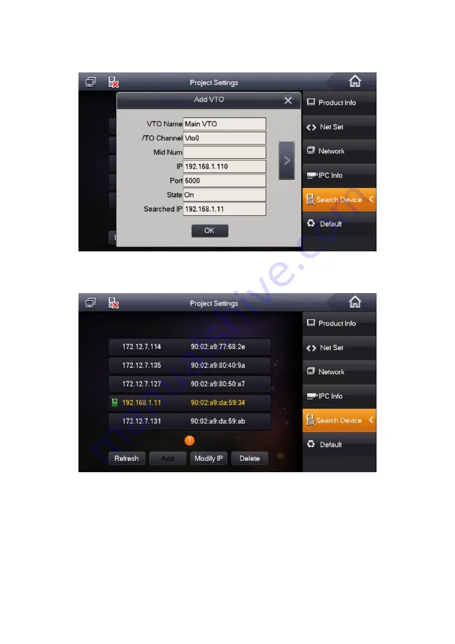
d)  Use 192.168.1.11 of the VTO to change default setup 192.168.1.110, change status as 

on. See Figure 2-16. 


Figure 2-16 


e)  Now you can see the following interface. See Figure 2-17. 


Figure 2-17 


Содержание VTO2000A Series

Страница 1: ...IP Villa System Quick Start Guide Version 1 0 0...

Страница 2: ......

Страница 3: ...ing transportation storage and installation 3 Installation Keep upwards Handle with care Do not apply power to the device before completing installation Do not place objects on the device 4 Qualified...

Страница 4: ...3 Add ONVIF Network Camera 13 3 4 Check Results 14 3 5 VTO Settings 14 3 5 1 Add Dahua Network Camera 14 3 5 2 Check Results 14 4 Cell Phone Settings 15 4 1 VTO Settings 15 4 2 Cell Phone Settings 15...

Страница 5: ...g at the same time You can call hang up and unlock on any of these VTHs 1 1 IP Connection Mode 1 This mode is for VTO2000A VTH1550CH VTH1560B VTH has one master VTH and up to three extension VTHs See...

Страница 6: ...st login 2 1 Change Default Password Please refer to Figure 2 1 to change VTO password Figure 2 1 Please refer to Figure 2 2 to change account password open door password arm disarm password an hijack...

Страница 7: ...5 Figure 2 3 b Now you can set local information See Figure 2 4 Figure 2 4 c Now you can add digital VTH System has added room 9901 by default See Figure 2 5 Figure 2 5...

Страница 8: ...anguage System supports English Russian Italian French Germany Dutch Spanish and Portuguese by default See Figure 2 7 After device booted up you can go to Settings Language 002236 to change language a...

Страница 9: ...d Click Network on the right pane and then input master VTO name IP address and enable current function Note Click to go to the extension VTO interface you can set extension VTO information You can se...

Страница 10: ...Product Info See Figure 2 10 Step2 Press Master Master icon becomes Extention icon Step3 Set Room No i e 9901 1 input IP Address Subnet Mask and Gateway Step4 In Master IP input IP of the master VTH...

Страница 11: ...information with the master VTH If one master VTH has several extension VTOs please enable status as on See Figure 2 12 Figure 2 12 2 5 Change Villa VTO IP via VTH a On the digital VTH interface from...

Страница 12: ...10 b Change VTO IP address as 192 168 1 11 See Figure 2 14 Figure 2 14 c Click Add to add VTO settings See Figure 2 15 Figure 2 15...

Страница 13: ...11 d Use 192 168 1 11 of the VTO to change default setup 192 168 1 110 change status as on See Figure 2 16 Figure 2 16 e Now you can see the following interface See Figure 2 17 Figure 2 17...

Страница 14: ...Figure 2 18 2 6 Check Results On the indoor VTO click monitor button you can view the situation of the VTO On the villa VTO click the Call button you can call any of the VTHs For the VTH from Video T...

Страница 15: ...me IP address port 5000 protocol local and then click Save button User name and password are the account for you to login the network camera See Figure 3 1 Figure 3 1 3 3 Add ONVIF Network Camera On t...

Страница 16: ...o switch to different network camera video See Figure 3 3 Figure 3 3 3 5 VTO Settings For the VTO it supports 24 network cameras It supports product from Dahua 3 5 1 Add Dahua Network Camera Please re...

Страница 17: ...the network Set local DNS address See Figure 4 1 Figure 4 1 b Go to P2P interface check the box to enable the P2P function Please wait until the status becomes on See Figure 4 2 Figure 4 2 4 2 Cell P...

Страница 18: ...16 b Use the cell phone to scan the QR code of VTO on the device s label or Web See Figure 4 4 and Figure 4 5 Figure 4 4 Figure 4 5...

Страница 19: ...O You can view the corresponding video from the VTO after it detects the device Figure 4 6 4 3 Check Results When the VTO is calling the VTH you can see a push message on your cell phone Open the mess...

Страница 20: ...4 2 25 Cross recessed pan head tail tapping screws stainless 4 FEC5 30 plastic expansion bolt 4 Figure 5 1 Figure 5 2 b Align the device on metal bracket according to screw hole Fasten screw M3 8 Cros...

Страница 21: ...re 5 1 5 1 2 Embedded in Wall a Dig a hole on wall its dimension is 117 128 80 mm See Figure 5 Figure 5 4 b Embed metal bracket into wall until its four peaks lean against the wall See Figure 5 2 Figu...

Страница 22: ...countersunk head tail machine screws galvanizing white and fix device on metal bracket See Figure 5 3 Component Name Icon No M3 8 Cross recessed countersunk head tail machine screws galvanizing white...

Страница 23: ...device on the installation bracket and then use the clip to secure See Figure 5 1 Component Name Icon No M4 30 crosshead pan head thread 3 Figure 5 1 5 2 2 Installation Mode 2 a Secure the installatio...

Страница 24: ...r end of the on off button to the GND of VTO See Figure 6 1 Electric Lock Unlock Button Power GND ALM1 NO COM Figure 6 1 6 2 Magnetic Door Lock When connect the VTO to the magnetic door lock connect t...

Страница 25: ...isplay Monitor dimensions 7 inch TFT true color screen Operation mode Input Touch buttons Alarm Alarm Input 6 channel local alarm input 8 channel local alarm input Alarm Output 1 channel local alarm o...

Страница 26: ...col TCP IP General Power DC 10V 15V or special switch to provide power directly Consumption Standby 1W working 10W Working Temperature 30 60 Relative Humidity 10 90 RH Dimensions L W H 129 9mm 32 2mm...

Страница 27: ......

Страница 28: ......

Отзывы: