background image

Household  Setting    26 

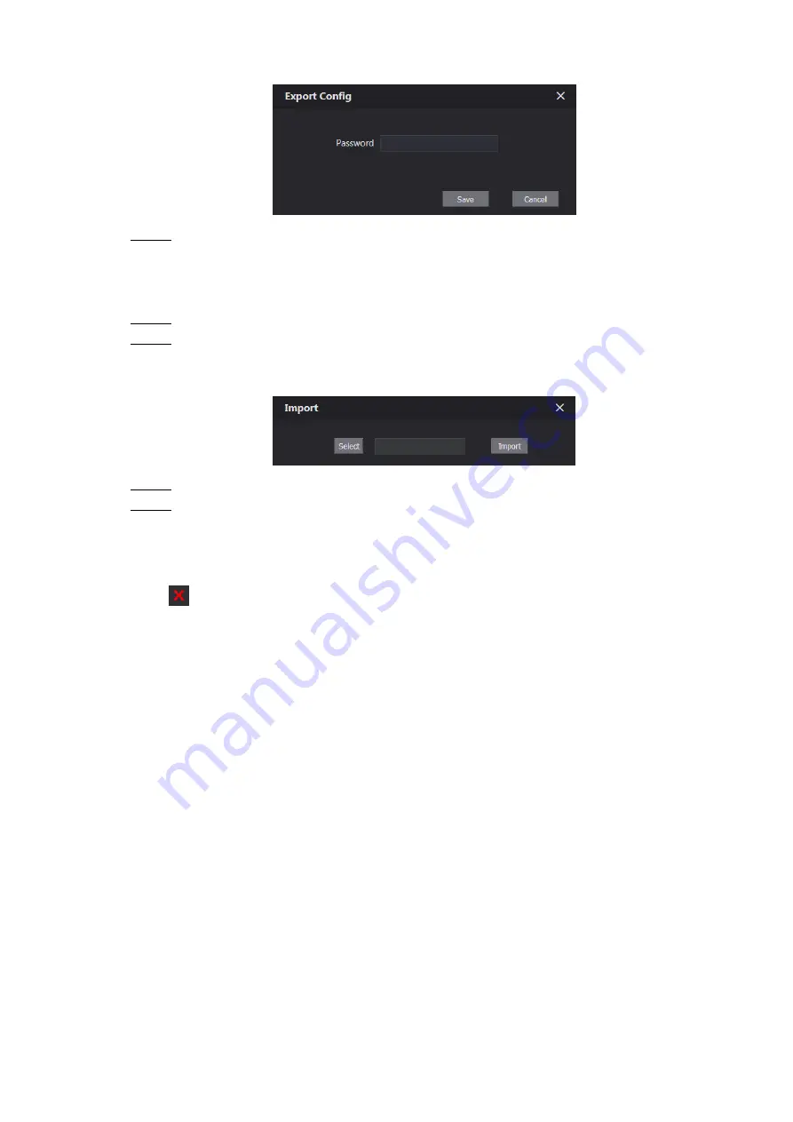
 Export config 

Figure 5-19


  Enter the password for the Web interface, and then click 

Save

 to export face data. 

Step 2

5.7.2 Importing Face Data 

  Click 

Face Info Import

Step 1

  Enter the password for the Web interface, and then click 

Save

Step 2

The Import interface is displayed. See Figure 5-20. 

 Import 

Figure 5-20


  Click 

Select

, and then select the file you need. 

Step 3

  Click 

Import

Step 4

5.7.3 Deleting Face Data 

Click 

  to delete single face data. 

Click 

Remove All

 to delete all the face data. 

Содержание Unit VTO6221E-P

Страница 1: ...Unit VTO Version 4 3 User s Manual V1 0 1 ...

Страница 2: ...egularly change the credentials to your devices to help ensure that only authorized users are able to access the system 2 Change Default HTTP and TCP Ports Change default HTTP and TCP ports for systems These are the two ports used to communicate and to view video feeds remotely These ports can be changed to any set of numbers between 1025 65535 Avoiding the default ports reduces the risk of outsid...

Страница 3: ...tem is set up for multiple users ensure that each user only has rights to features and functions they need to use to perform their job 10 UPnP UPnP will automatically try to forward ports in your router or modem Normally this would be a good thing However if your system automatically forwards the ports and you leave the credentials defaulted you may end up with unwanted visitors If you manually fo...

Страница 4: ...eras to the PoE Ports on the Back of an NVR Cameras connected to the PoE ports on the back of an NVR are isolated from the outside world and cannot be accessed directly 16 Isolate NVR and IP Camera Network The network your NVR and IP camera resides on should not be the same network as your public computer network This will prevent any visitors or unwanted guests from getting access to the same net...

Страница 5: ...mber GPS and so on You need to be in compliance with the local privacy protection laws and regulations to protect the legitimate rights and interests of other people by implementing measures include but not limited to providing clear and visible identification to inform data subject the existence of surveillance area and providing related contact About the Manual The Manual is for reference only I...

Страница 6: ... is any doubt or dispute please refer to our final explanation Upgrade the reader software or try other mainstream reader software if the Manual in PDF format cannot be opened All trademarks registered trademarks and the company names in the Manual are the properties of their respective owners Please visit our website contact the supplier or customer service if there is any problem occurred when u...

Страница 7: ...on t put on the device anything filled with liquids in order to prevent liquids from flowing into the device Please install the device at well ventilated places don t block its ventilation opening Use the device only within rated input and output range Please don t dismantle the device arbitrarily Please transport use and store the device within allowed humidity and temperature range Power Require...

Страница 8: ...nd 13 4 6 Face Recognition 14 4 7 5 Household Setting 15 VTO No Management 15 5 1 5 1 1 Adding VTO 15 5 1 2 Modifying VTO 16 5 1 3 Deleting VTO 17 Room No Management 17 5 2 5 2 1 Adding Room Number 17 5 2 2 Modifying Room Number 19 5 2 3 Issuing Access Card 19 VTS Management 20 5 3 IPC Setting 22 5 4 Status 23 5 5 Publish Information 24 5 6 5 6 1 Send Info 24 5 6 2 History Info 24 Face Management ...

Страница 9: ...Table of Contents VIII FTP 27 6 2 UPnP 28 6 3 SIP Server 30 6 4 IP Permissions 31 6 5 7 Log Management 33 Call 33 7 1 Alarm 33 7 2 Unlock 34 7 3 Log 34 7 4 ...

Страница 10: ...r the default IP address of the VTO in Step 2 the address bar and then press Enter The Device Init interface is displayed See Figure 1 1 Device initialization Figure 1 1 Enter and confirm the password and then click Next Step 3 The Email setting interface is displayed Select the Email check box and then enter your Email address This Email address Step 4 can be used to reset the password and it is ...

Страница 11: ...Initialization 2 Login interface Figure 1 2 ...

Страница 12: ...The login interface is displayed See Figure 2 1 Login interface Figure 2 1 Enter admin as username then the password you set during initialization and then Step 2 click Login Resetting Password 2 2 On the login interface Figure 2 1 click Forgot Password Step 1 The Reset the password 1 3 dialog box is displayed See Figure 2 2 Reset the password 1 3 Figure 2 2 Click Next Step 2 The Reset the passwor...

Страница 13: ...he supplier or customer service for help To obtain security code again refresh QR code interface Use the security code within 24 hours after receiving it Otherwise it will become invalid If wrong security code is entered for 5 times continuously this account will be locked for 5 min Click Next and then the Reset the password 3 3 dialog box is displayed Step 4 Set and confirm the new password as in...

Страница 14: ...d and your Email address Click to go to the main interface Click to log out reboot the VTO or restore the VTO to factory settings 2 VTO information You can view the general information of the VTO including building No unit No device type and VTO No 3 System information You can view the software version MCU version and security baseline version 4 Config manager Select Device Info or User Info and t...

Страница 15: ...igure 3 1 select Local Setting Basic Step 1 The Basic interface is displayed See Figure 4 1 Basic Figure 4 1 Configure parameters and for the detailed description see Table 4 1 Step 2 Table 4 1 Basic parameter description Parameter Description Device Type You can select Unit Door Station or Fence Station Unit Door Station Normally installed inside the community with a specific building number or u...

Страница 16: ...aved to the FTP server automatically Auto Snapshot unlock Select ON to enable this function and then the system takes snapshot every time when the door is unlocked Auto Snapshot talking Select ON to enable this function and then the system takes snapshot every time when VTH user answers a call from the VTO Leave Message Upload Select ON to enable this function and then the system uploads the messa...

Страница 17: ...quality will be Sub Stream Video Format Select the video resolution from CIF WVGA QVGA and D1 Format Rate Configure the number of frames in 1 second You can select from 1 to 25 under PAL and 1 to 30 under NTSC The larger the value is the smoother the video will be Bitrate Rate Configure the data amount that transmitted in 1 second You can select as needed The larger the value is the better the vid...

Страница 18: ...Hue Makes the color deeper or lighter The default value is made by the light sensor and it is recommended Saturation Makes the color deeper or lighter The larger the value is the deeper the color will be and the lower the lighter Saturation value doesn t change image brightness Gamma Changes the picture brightness and improves the picture dynamic range in a non linear way The larger the value is t...

Страница 19: ...alarm will be sent to the management center Select the Enable check box and the door will not be locked until the door sensor contacts each other If you do not select the Enable check box the door will be locked after the Unlock Period finishes Issue Card Password This password can be used to issue new card This password is only for admin people or engineer It is 888888 by default Project Password...

Страница 20: ...nterface Type Step 2 list For the detailed description see Table 4 4 Table 4 4 RS 485 access control parameter description Parameter Description Lock Unlock Responding Interval The time interval to unlock again after the previous unlock and the unit is second Unlock Period The time amount for which the lock stays open after unlock and the unit is second Second Unlock Command You can connect a thir...

Страница 21: ... parameter description Parameter Description Date format You can select from Year Month Day Month Day Year and Day Month Year Time format Configure the time format and you can select from 12 Hour or 24 Hour System Time Configure the VTO system date time and time zone Do not change the system time arbitrarily it might cause problems on video searching and publishing snapshot or notice Before changi...

Страница 22: ...ace Figure 3 1 select Local Setting Security Step 1 The Security interface is displayed See Figure 4 6 Security Figure 4 6 Configure parameters and for the detailed description see Table 4 6 Step 2 Table 4 6 Security parameter description Parameter Description CGI Enable Select the check box to enable and then you can use CGI command Reset Password Select the check box to enable and then the passw...

Страница 23: ...ce is displayed See Figure 4 8 Face recognition Figure 4 8 Configure face recognition parameters See Table 4 8 Step 2 Table 4 8 Face recognition parameter description Parameter Description Face Threshold The larger the value is the more similar the target and the saved face data is required to open the door Anti False Threshold The larger the value is the less the chance that the system defines a ...

Страница 24: ...rvers as SIP server see the corresponding manual for the detailed configuration VTO No Management 5 1 5 1 1 Adding VTO You can add VTO devices to the SIP server and all the VTO devices connected to the same SIP server can make video call between each other Log in the web interface of the SIP server and then select Household Setting VTO Step 1 No Management The VTO No Management interface is displa...

Страница 25: ... in Table 4 1 Register Password Keep default value Build No Available only when other servers work as SIP server Unit No IP Address The IP address of the target VTO Username The user name and password for the WEB interface of the target VTO Password Click Save Step 4 5 1 2 Modifying VTO The VTO that is currently at use cannot be modified or deleted On the VTO No Management interface Figure 5 1 cli...

Страница 26: ...nagement interface Figure 5 1 click to delete VTO one by one and click Clear to delete all the VTO Room No Management 5 2 5 2 1 Adding Room Number You can add the planned room number to the SIP server and then configure the room number on VTH devices to connect them to the network Log in the web interface of the SIP server and then select Household Setting Room Step 1 No Management The Room No Man...

Страница 27: ...terface is displayed See Figure 5 5 Add single room number Figure 5 5 2 Configure room information and for the detailed description See Table 5 2 Table 5 2 Room information Parameter Description First Name Enter the information you need to differentiate each room Last Name Nick Name Room No The room number you planned Register Type Select public and local is reserved for future use ...

Страница 28: ... room numbers are displayed Click Refresh to view the latest status and click Clear to delete all the room numbers 5 2 2 Modifying Room Number On the Room No Management interface Figure 5 4 click Step 1 The Modify interface is displayed See Figure 5 6 Modify room number Figure 5 6 You can modify the names for the room See Table 5 2 for the details Step 2 Click Save Step 3 5 2 3 Issuing Access Card...

Страница 29: ... to issue access card for this room on the VTO Click again to resume Click to set it to the lost state and then the icon turns into The card under lost state cannot be used to open the door Click again to resume Click to modify the user name Click to delete the card VTS Management 5 3 You can add VTS device to the SIP server and the VTS can be used as the management center It can manage all the VT...

Страница 30: ...s and for the detailed description see Table 5 3 Step 4 Table 5 3 Add VTS configuration Parameter Description VTS No The VTS number you configured for the target VTS Register Password Keep default value IP Address The IP address of the target VTS Click Save and then the added VTS is displayed Click to modify IP address and Step 5 click to delete Select Local Setting Basic then enter the VTS No of ...

Страница 31: ...can do monitor with the added cameras Log in the web interface of the SIP server and then select Household Setting IPC Step 1 Setting The IPC Setting interface is displayed See Figure 5 13 IPC setting Figure 5 13 The total quantity of the device you can add is fixed and you can click to add the Step 2 device you need The Modify interface is displayed See Figure 5 14 ...

Страница 32: ...r Extra1 and the main stream has better image quality but also costs more bandwidth Channel Define a channel for the device Device Type Select from IPC NVR HCVR and XVR as needed Click Save and then the added device is displayed Click to modify and click Step 4 to delete You can also click Export Config to export the current devices to the local PC or click Import Config to import the existed conf...

Страница 33: ... select All device to send the message to all the devices in Step 2 the network and then the title and content of your message If you want to send information to more than one VTH VTH numbers should be separated by semicolons For example if you enter 101 102 103 and more and VTH of these VTH numbers will receive information sent by the VTO The Period of validity is reserved for future use Click Co...

Страница 34: ...and export face data Face recognition is available on select models The VTO can save 10 000 faces at most Select Household Setting Face Management The Face Management interface is displayed See Figure 5 18 Face management Figure 5 18 5 7 1 Exporting Face Data Click Face Info Export Step 1 The Export Config interface is displayed See Figure 5 19 ...

Страница 35: ...Face Data Click Face Info Import Step 1 Enter the password for the Web interface and then click Save Step 2 The Import interface is displayed See Figure 5 20 Import Figure 5 20 Click Select and then select the file you need Step 3 Click Import Step 4 5 7 3 Deleting Face Data Click to delete single face data Click Remove All to delete all the face data ...

Страница 36: ...meters and port number you planed and then click Save Step 2 The VTO will reboot and you need to modify the IP address of your PC to the same network segment as the VTO to log in again 6 1 2 HTTPS Select the Enable check box at HTTPS Port and then the VTO will reboot After rebooting you can log in the VTO by entering https VTO IP address in the address bar of the explorer FTP 6 2 Configure FTP ser...

Страница 37: ...default Username The username and password of the FTP server Password Click Save Step 3 UPnP 6 3 Universal Plug and Play a protocol that establishes mapping relation of ports in LAN and WAN This function enables you to visit local area device through wide area network This function is valid only when VTO works as SIP server This function is needed only when the VTO is connected to a router with UP...

Страница 38: ...a new one The Modify Add interface is displayed See Figure 6 4 Modify Add UPnP Figure 6 4 Configure parameters See Table 6 2 Step 4 Table 6 2 UPnP parameter description Parameter Description ON OFF Select ON to enable this mapping relation Service Name The name of the service Service Type Define the type of the service as needed Protocol You can select from TCP and UDP For the transmission stabili...

Страница 39: ...hen you can visit the local area device with corresponding port SIP Server 6 4 The SIP server is required in the network to transmit intercom protocol and then all the VTO and VTH devices connected to the same SIP server can make video call between each other You can use VTO device or other servers as SIP server Select Network Setting SIP Server Step 1 The SIP Server interface is displayed See Fig...

Страница 40: ...nual for the detailed configuration IP Permissions 6 5 To enhance network and data security you need to configure access authority for different IP addresses Select Network Setting IP Permissions Step 1 The IP Permissions interface is displayed See Figure 6 6 IP Permissions Figure 6 6 Click Step 2 The White List option and Black List option are displayed See Figure 6 7 White List and Black List Fi...

Страница 41: ...List and then add an IP address or IP section in the white list before clicking Confirm Click Add Step 4 The Add interface is displayed See Figure 6 8 Add IP address Figure 6 8 You can select and enter single IP address or an IP section and then click Save Step 5 ...

Страница 42: ...e Call interface is displayed See Figure 7 1 Call Figure 7 1 Click Export Data to export the records to your PC Alarm 7 2 This function is displayed only when the VTO you are visiting works as SIP server and you can view the VTO and VTH alarm record and duress password alarm record Select Log Management Alarm The Alarm interface is displayed See Figure 7 2 Alarm Figure 7 2 Click Export Data to exp...

Страница 43: ...d See Figure 7 3 Unlock Figure 7 3 Click Export Data to export the records to your PC Log 7 4 You can view various system logs including system record config account and security Select Log Management Log Step 1 The Log interface is displayed See Figure 7 4 Log Figure 7 4 Configure the time range then select the log type you need and then click Search Step 2 Click Export Data to export the records...

Отзывы: