


6
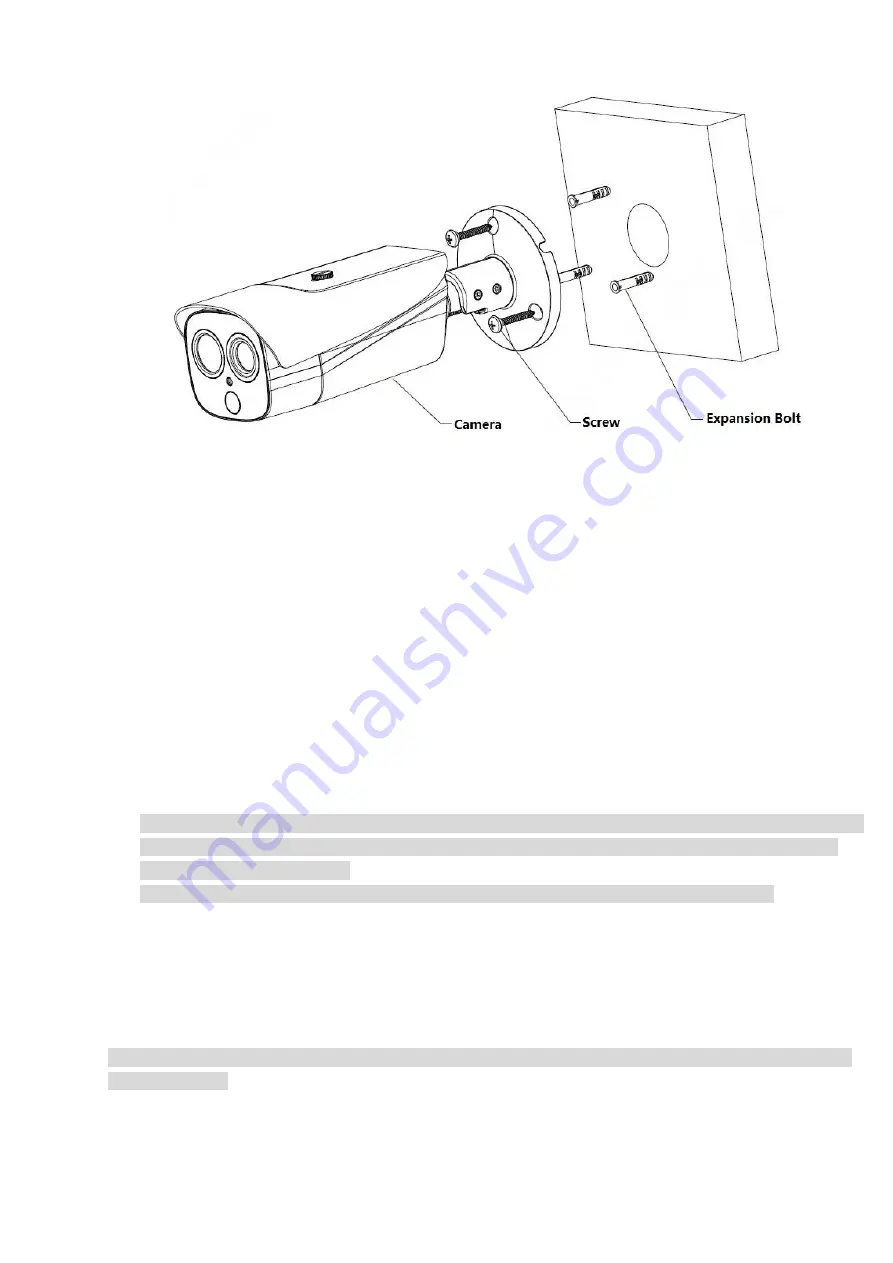
Figure 3-1
Step 1
Fix the device on the mounting surface.
1. Take out the installation position map from the accessory bag, stick it on the surface which needs to be
installed (wall or ceiling), and then dig holes according to the hole sites marked on the installation
position map.
2. Take out the expansion bolts from the accessory bag and then insert them into the holes.
3. Take out the self-tapping screws from the accessory bag, align the mounting holes on the device bracket
chassis with the expansion bolts which have been well inserted, and use self-tapping screws to fix the
device on the mounting surface (wall or ceiling).
Step 2
Connect the external cable well according to the requirements.
1. Connect the corresponding power, video output and other ports well according to requirements, and
then use insulated rubber tape to twine the connection joint well to make it waterproof.
Note
The video port is covered with heat-shrinkable tube with high shrinkage ratio, it needs to heat and shrink
the tubes on both sides after the video port is well connected, which is to make sure the video port is
moistureproof and waterproof.
The grounding hole is recommended to be grounded, which is to enhance device reliability.
2. It is to install waterproof cover for network port according to actual implementation by referring to step 3.
3. Please refer to 4.4 Alarm Setup for alarm input and output cable connection and config.
4. It can properly lengthen device cable according to actual construction requirements.
Step 3
(Optional) Install waterproof connector for network port.
Note
It needs to implement the following operation when the device is equipped with waterproof connector and it
is used outdoors.
Содержание TPC-BF2120-1F4
Страница 1: ...Thermal Hybrid Bullet Network Camera Quick Start Guide Version 1 0 0 ...
Страница 11: ...1 ...
Страница 23: ...13 Figure 5 2 Step 3 Click Save to save config ...