Dahua Pinhole Скачать руководство пользователя страница 16


Dahua HD Pinhole Network Camera Quick Start Guide  


11 

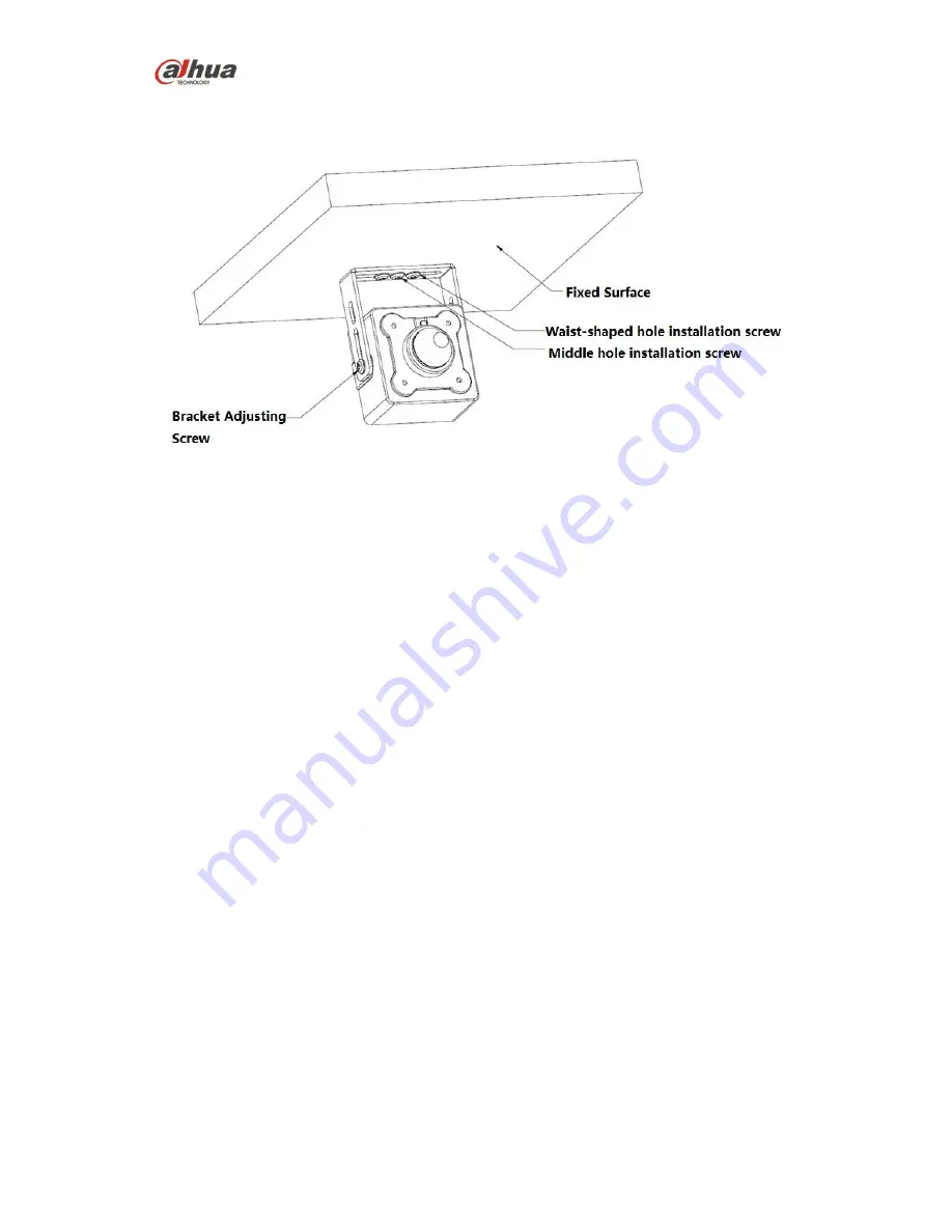
Figure 2-5 Installation of device 


Install the camera

:  

Use screws to fix the camera on the installation wall, as it is shown in Figure 2-1.  

Location /angle adjustment:  

1.  Install the camera on the fixed wall together with the bracket.  


The screw is installed in the middle hole, and then the camera can rotate.  


The screw is installed in the left and right waist-shaped holes, and then the camera can 

be adjusted rightward and leftward.  

2.  Loosen the bracket adjusting screw to adjust the camera angle.  

Содержание Pinhole

Страница 1: ...Dahua HD Pinhole Network Camera Quick Start Guide Dahua HD Pinhole Network Camera Quick Start Guide Version 1 0 0 Dahua Vision Technology Co Ltd ...

Страница 2: ...it might result in device damage We assume no liability or responsibility for all the fires or electrical shock caused by improper handling or installation We are not liable for any problems caused by unauthorized modification or attempted repair 2 Environment Do not aim the device at strong light such as lighting sunlight and so on to focus otherwise it might cause overexposure not the device mal...

Страница 3: ...e oil free soft brush or air blower to gently wipe it away If stained with grease or fingerprint firstly use soft cloth to gently wipe the water drop or oil and wait till it is dry and then use oil free cotton cloth or leans cleaning paper soaked with alcohol or detergent to wipe from the lens center outward till it is clean Warning Please modify the default password after login to avoid being sto...

Страница 4: ...is no guarantee that interference will not occur in a particular installation If this equipment does cause harmful interference to radio or television reception which can be determined by turning the equipment off and on the user is encouraged to try to correct the interference by one or more of the following measures Reorient or relocate the receiving antenna Increase the separation between the e...

Страница 5: ... 1 2 Structure and Dimension of All in one Pinhole Network Camera 4 1 2 Bidirectional Talk 5 1 2 1 Device end to PC end 5 1 2 2 PC end to the Device end 6 1 3 Alarm Setup 6 2 Device Installation 8 2 1 Installation of HD Modular Pinhole Network Camera 8 2 2 Installation of HD All in one Pinhole Network Camera 10 3 Network Configuration 12 3 1 Modify IP Address 12 3 2 Login WEB Interface 13 ...

Страница 6: ...he actual products and the corresponding figures so please refer to the actual products you purchased 1 1 1 Structure and Dimension of Modular Pinhole Network Camera 1 1 1 1 Structure You can refer to the following figures for port information See 错误 未找到引用源 and Figure 1 2 Figure 1 1 Ports of the device 1 Figure 1 2 Ports of the device 2 Please refer to the table 1 1 for detailed information about ...

Страница 7: ...Power input port Power port input DC12 V or POE power supply 7 I O I O port Connect I O port 8 Reset Button Reset It is used to restore factory default settings for the device Note Continuously press the button for over 5 seconds in the situation where the device is working normally then the system configuration info can be restored to factory default settings Please refer to table 1 2 for more de...

Страница 8: ...igures for dimension information of different models for modular pinhole camera The unit is mm Please refer to Figure 1 3 for the dimension of model A Figure 1 3 Dimension of model A Please refer to Figure 1 4 for the dimension of model B Figure 1 4 Dimension of model B Figure 1 5 Dimension of model C ...

Страница 9: ...of rear end Please refer to Figure 1 6 for the dimension of rear end for the three models described above 1 1 2 Structure and dimension of All in one Pinhole Network Camera You can refer to the following figures for more details See Figure 1 7 Figure 1 7 Dimension of device ...

Страница 10: ...ignal from the environment 2 Back cover 3 Binding wire It is used to fix the cable 4 Network port Connect to standard Ethernet cable 5 Power input port Power port input DC 12V 6 Bracket It is used to fix the camera 7 Bracket adjusting screw It is used to adjust the camera angle 8 Front cover 1 2 Bidirectional Talk Note This function is only supported by HD modular pinhole network camera 1 2 1 Devi...

Страница 11: ...ker or the MIC to the audio input port of the PC and then connect the earphone to the audio output port of the device Login the Web and then click the Talk button to enable the bidirectional talk function You can see the button becomes orange after you enabled the audio talk function Click Talk button again to stop the bidirectional talk function Note The on site listening operation is null during...

Страница 12: ...ice 3 Open the Web set alarm input and output correspondingly Alarm input 01 on WEB corresponds to the first alarm input of I O cable on device When there is alarm alarm input device will generate signal of high and low level Set corresponding NO and NC inputs 4 Set the WEB alarm output The alarm output corresponds to the first channel alarm output of I O port on the device ...

Страница 13: ...tion surface can min support the 3X weight of the camera and the bracket Refer to the followings steps for the installation of round and square rear end Figure 2 1 Installation of round and square rear end 1 Stick installation position map to designated surface where you will install the device 2 Dig a hole according to position of hole on installation position map 3 Open accessories bag take out ...

Страница 14: ... foam 2 Tear off the film of the foam and stick it on the surface to be installed 3 Set the fixing ring on the installation bracket 4 Put the round front end into the installation bracket and adjust the location 5 Tighten the fixing ring There are two installation modes for square front end as follows Installation mode 1 Figure 2 3 Installation mode 1 for square front end ...

Страница 15: ... installation expansion bolts on the installation surface 2 Take out the expansion bolts from the accessories bag and nail them into the holes you just dug 3 Open the accessories bag and take out the screws tighten the three screws and fix the device on the installation surface where the bolts are located 4 Take out the decoration enclosure from the accessories bag aim the device and press it hard...

Страница 16: ...shown in Figure 2 1 Location angle adjustment 1 Install the camera on the fixed wall together with the bracket The screw is installed in the middle hole and then the camera can rotate The screw is installed in the left and right waist shaped holes and then the camera can be adjusted rightward and leftward 2 Loosen the bracket adjusting screw to adjust the camera angle ...

Страница 17: ...l introduce the approach of modifying IP address via Quick Configuration Tool also you can modify the IP address in the network parameters of the WEB interface please refer to the document in the disk WEB Operation Manual for more details Note Currently the quick configuration tool only supports the cameras which apply to the same network segment with computer IP address 1 Double click the ConfigT...

Страница 18: ...Figure 3 2 Network parameters 3 2Login WEB Interface Note Different devices may have different WEB interfaces the figures below are just for reference please refer to the document WEB Operation Manual in the disk and the actual interface for more details 1 Open IE and input the modified camera IP address in the address bar See Figure 3 3 for more details Figure 3 3 Login ...

Страница 19: ...ged in Figure 3 4 WEB main screen Note This quick start guide is for reference only Minor differences might be found in user interface All the designs and software are subject to change without prior written notice If there is any uncertainty or controversy please refer to our final explanation Please visit our website or contact your local service engineer for more information Dahua Vision Techno...

Отзывы: