129
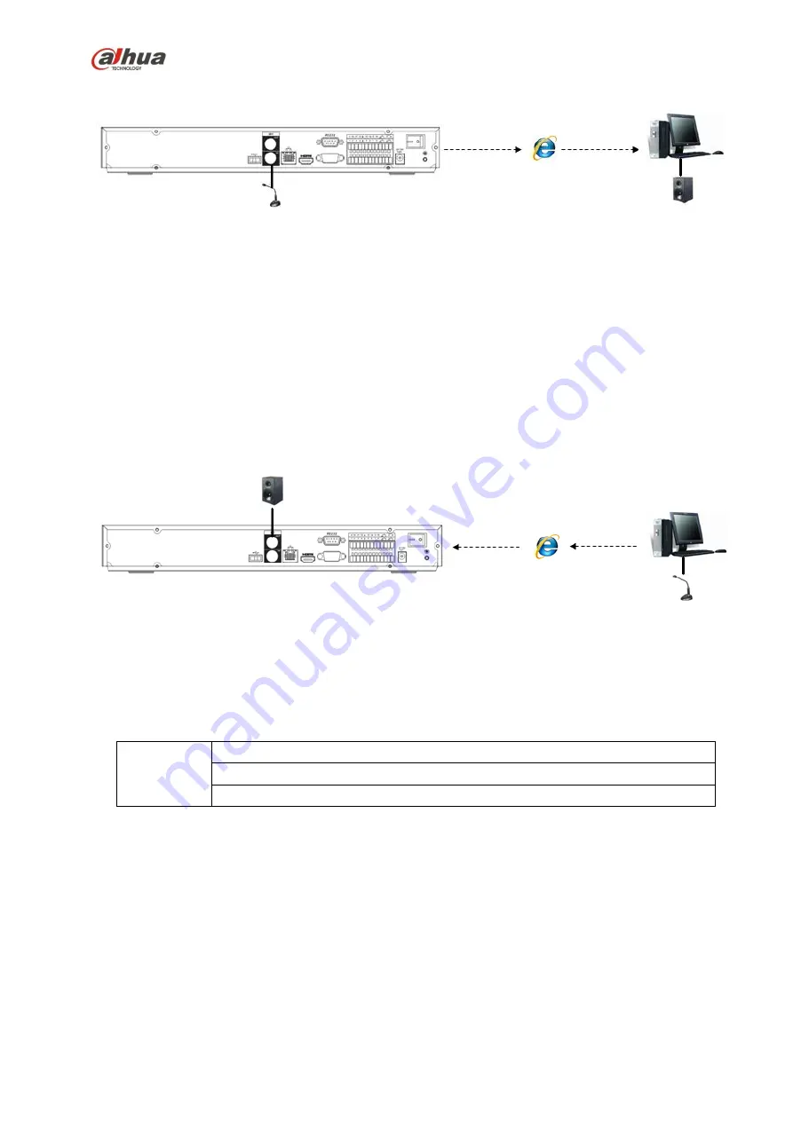
or sound box at the pc-end. See Figure 2-83.
Figure 2-83
2.4.2
PC-end to the device-end
Device Connection
Connect the speaker or the pickup to the audio output port in the PC and then connect the earphone or
the sound box to the first audio input port in the device rear panel.
Login the Web and then enable the corresponding channel real-time monitor.
Please refer to the above interface (Figure 2-82) to enable bidirectional talk.
Listening Operation
At the PC-end, speak via the speaker or the pickup, and then you can get the audio from the earphone or
sound box at the device-end. See Figure 2-84.
Figure 2-84
2.5 Mouse Operation
Please refer to the following sheet for mouse operation instruction.
Left
click
mouse
When you have selected one menu item, left click mouse to view menu content.
Modify checkbox or motion detection status.
Click combo box to pop up dropdown list
Содержание nvr4208-8p
Страница 1: ...Dahua Network Video Recorder User s Manual V 2 7 0 ...
Страница 159: ...144 Figure 3 3 3 5 4 NVR11HS 41HS W S2 Series Please refer to Figure 3 4 for connection sample ...
Страница 160: ...145 Figure 3 4 3 5 5 NVR41HS W S2 Series Please refer to Figure 3 5 for connection sample ...
Страница 163: ...148 Figure 3 7 3 5 8 NVR42N Series Please refer to Figure 3 8 for connection sample Figure 3 8 ...
Страница 171: ...156 Figure 3 18 3 5 19 NVR78 Series Please refer to Figure 3 19 for connection sample ...
Страница 172: ...157 Figure 3 19 3 5 20 NVR78 16P Series Please refer to Figure 3 20 for connection sample ...
Страница 173: ...158 Figure 3 20 3 5 21 NVR78 RH Series Please refer to Figure 3 21 for connection sample ...
Страница 174: ...159 Figure 3 21 3 5 22 NVR70 Series Please refer to Figure 3 22 for connection sample ...
Страница 175: ...160 Figure 3 22 3 5 23 NVR70 R Series Please refer to Figure 3 23 for connection sample ...
Страница 176: ...161 Figure 3 23 3 5 24 NVR42V 8P Series Please refer to Figure 3 24 for connection sample ...
Страница 177: ...162 Figure 3 24 ...
Страница 188: ...173 Figure 4 19 Click smart add button you can see device enables DHCP function See Figure 4 20 Figure 4 20 ...
Страница 243: ...228 Figure 4 89 Figure 4 90 ...
Страница 244: ...229 Figure 4 91 Figure 4 92 ...
Страница 259: ...244 Figure 4 110 Figure 4 111 ...
Страница 260: ...245 Figure 4 112 Figure 4 113 ...
Страница 261: ...246 Figure 4 114 Figure 4 115 ...
Страница 263: ...248 Figure 4 117 Figure 4 118 ...
Страница 290: ...275 Figure 4 148 In Figure 4 148 click one HDD item the S M A R T interface is shown as in Figure 4 149 Figure 4 149 ...
Страница 355: ...340 Figure 5 55 Figure 5 56 ...
Страница 356: ...341 Figure 5 57 Figure 5 58 Figure 5 59 ...
Страница 367: ...352 Figure 5 73 Figure 5 74 ...


