177
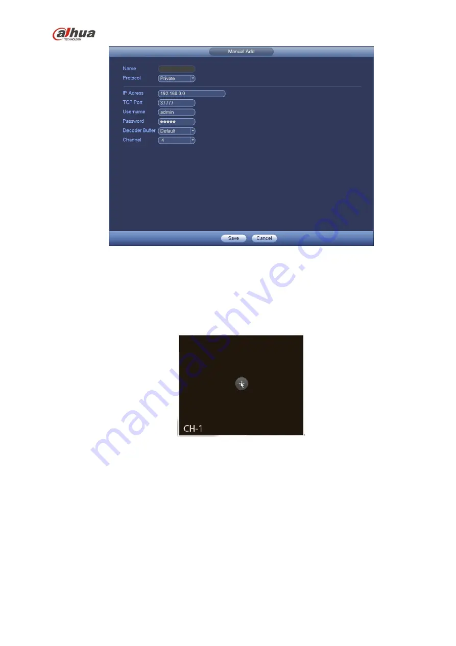
Figure 4-25
4.6.2
Short-Cut Menu
In the preview interface, for the channel of no IP
C connection, you can click the icon “+” in the centre of
the interface to quickly go to the registration interface (Figure 4-24.). See Figure 4-26.
Figure 4-26
4.6.3
Image
From main menu->setting->camera->image, you can see the image interface is shown as below. See
Channel: Select a channel from the dropdown list.
Saturation: It is to adjust monitor window saturation. The value ranges from 0 to 100. The default
value is 50. The larger the number, the strong the color is. This value has no effect on the general
brightness of the whole video. The video color may become too strong if the value is too high. For
the grey part of the video, the distortion may occur if the white balance is not accurate. Please note
the video may not be attractive if the value is too low. The recommended value ranges from 40 to 60.
Содержание NVR4204-P-4KS2
Страница 159: ...144 Figure 3 3 3 5 4 NVR11HS 41HS W S2 Series Please refer to Figure 3 4 for connection sample ...
Страница 160: ...145 Figure 3 4 3 5 5 NVR41HS W S2 Series Please refer to Figure 3 5 for connection sample ...
Страница 163: ...148 Figure 3 7 3 5 8 NVR42N Series Please refer to Figure 3 8 for connection sample Figure 3 8 ...
Страница 171: ...156 Figure 3 18 3 5 19 NVR78 Series Please refer to Figure 3 19 for connection sample ...
Страница 172: ...157 Figure 3 19 3 5 20 NVR78 16P Series Please refer to Figure 3 20 for connection sample ...
Страница 173: ...158 Figure 3 20 3 5 21 NVR78 RH Series Please refer to Figure 3 21 for connection sample ...
Страница 174: ...159 Figure 3 21 3 5 22 NVR70 Series Please refer to Figure 3 22 for connection sample ...
Страница 175: ...160 Figure 3 22 3 5 23 NVR70 R Series Please refer to Figure 3 23 for connection sample ...
Страница 176: ...161 Figure 3 23 3 5 24 NVR42V 8P Series Please refer to Figure 3 24 for connection sample ...
Страница 177: ...162 Figure 3 24 ...
Страница 188: ...173 Figure 4 19 Click smart add button you can see device enables DHCP function See Figure 4 20 Figure 4 20 ...
Страница 243: ...228 Figure 4 89 Figure 4 90 ...
Страница 244: ...229 Figure 4 91 Figure 4 92 ...
Страница 259: ...244 Figure 4 110 Figure 4 111 ...
Страница 260: ...245 Figure 4 112 Figure 4 113 ...
Страница 261: ...246 Figure 4 114 Figure 4 115 ...
Страница 263: ...248 Figure 4 117 Figure 4 118 ...
Страница 290: ...275 Figure 4 148 In Figure 4 148 click one HDD item the S M A R T interface is shown as in Figure 4 149 Figure 4 149 ...
Страница 355: ...340 Figure 5 55 Figure 5 56 ...
Страница 356: ...341 Figure 5 57 Figure 5 58 Figure 5 59 ...
Страница 367: ...352 Figure 5 73 Figure 5 74 ...


