342
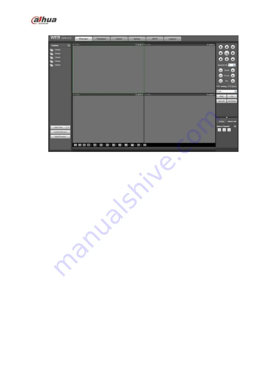
Figure 5-21
Important
The window display mode and the channel number are by default. For example, for the 16-channel,
the max window split mode is 16.
3) Multiple-channel monitor, system adopts extra stream to monitor by default. Double click one channel,
system switches to single channel and system uses main stream to monitor. You can view there are two
icons at the left top corner of the channel number for you reference. M stands for main stream. S stands
for sub stream (extra stream).
4) If you login via the WAN mode, system does not support alarm activation to open the video function in
the Alarm setup interface.
Important
For multiple-channel monitor mode, system adopts extra stream to monitor by default. You cannot
modify manually. All channels are trying to synchronize. Please note the synchronization effect still
depends on your network environments.
For bandwidth consideration, system cannot support monitor and playback at the same time. System
auto closes monitor or playback interface when you are searching setup in the configuration interface.
It is to enhance search speed.
5.10 Setup
5.10.1
Camera
5.10.1.1 Registration
5.10.1.1.1 Registration
From Main menu->Setting->Camera->Registration->Registration, you can see the following interface.
See Figure 5-22.
Содержание NVR1A-4P Series
Страница 1: ...Dahua Network Video Recorder User s Manual V 4 3 0 ...
Страница 138: ...124 Figure 3 5 3 6 6 NVR42N Series Please refer to Figure 3 6 for connection sample Figure 3 6 ...
Страница 142: ...128 Figure 3 11 3 6 12 NVR42V 8P Series Please refer to Figure 3 12 for connection sample ...
Страница 143: ...129 Figure 3 12 ...
Страница 157: ...143 Figure 4 15 Step 2 Click device display edit interface See Figure 4 16 ...
Страница 220: ...206 Figure 4 93 Figure 4 94 ...
Страница 240: ...226 Figure 4 110 Figure 4 111 Figure 4 112 ...
Страница 251: ...237 Figure 4 123 Figure 4 124 ...
Страница 253: ...239 Figure 4 126 Click draw button to draw the zone See Figure 4 127 ...
Страница 257: ...243 Figure 4 130 Click Draw button to draw a zone See Figure 4 131 Figure 4 131 ...
Страница 262: ...248 Figure 4 136 Click draw button to draw the zone See Figure 4 137 ...
Страница 275: ...261 Figure 4 148 Figure 4 149 ...
Страница 276: ...262 Figure 4 150 Figure 4 151 ...
Страница 387: ...373 Figure 5 60 Figure 5 61 ...
Страница 388: ...374 Figure 5 62 Figure 5 63 ...
Страница 412: ...398 Figure 5 96 Figure 5 97 ...
Страница 418: ...404 Figure 5 106 5 10 4 4 Record Control The interface is shown as in Figure 5 107 Figure 5 107 ...


