10
4.1 Installing the Camera
1. Remove the camera, the mounting template, and the hardware package from the box.
2. Apply the mounting template to the installation medium. Pre-drill the four (4) perimeter holes as
marked on the template for the expansion bolts, using a drill bit that is no wider than the
expansion bolt.
3. If routing wires through the installation medium, drill the center hole to route the cables from the
camera through the installation medium.
4. Insert an expansion bolt into each pre-drilled perimeter hole.
5. Turn the decoration ring clockwise to release it from the dome pedestal.
6. Pull the cables through the installation medium.
7. Align the three (3) screw holes in the pedestal to the three (3) plastic expansion bolt holes in the
installation medium, and then insert a self-tapping screw into each expansion bolts and secure
firmly.
8. Place the decoration ring back onto the pedestal and rotate counter-clockwise until a snap is
heard indicating the ring is secured to the pedestal.
9. Connect the external cables from the camera to the appropriate cables for Ethernet and power.
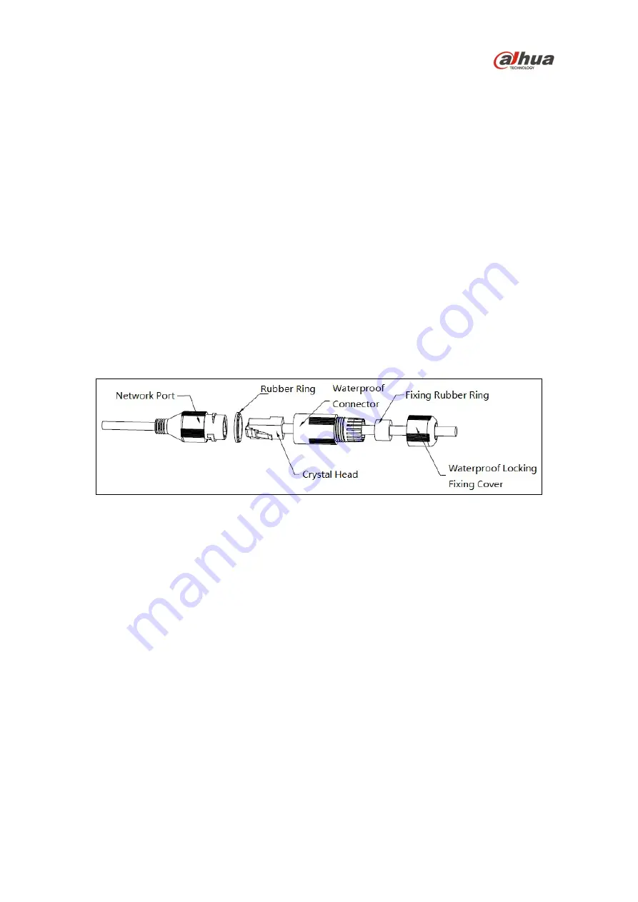
10. Attach the waterproof network connector if the camera is used outdoors.
Figure 4-2
a) Place the wide side of the rubber ring onto the end of the network cable extending out
from the camera.
b) Pull the waterproof cable end without the Ethernet connector through the body of the
Waterproof Connector. Thread the cable through the Fixing Rubber Ring and the
Waterproof Locking Cover.
c) Attach the male Ethernet connector to the network cable coming from the camera. Ensure
the Waterproof Connector shroud covers the Ethernet connection.
d) Connect the other end of the waterproof connector to the network port and rotate it
clockwise to lock the network port and waterproof connector firmly.
e) Slide the Waterproof Locking Cover over the main body of waterproof connector and
rotate it clockwise to seal the connection.
11. Supply power to the camera.


