Dahua IPC-HDW3849H-AS-PV-0280B Скачать руководство пользователя страница 7

Quick Start Guide 

Table 1-2 Alarm information 

Port 

Port Name 

Description 

Alarm I/O 

ALARM_OUT 

Outputs alarm signal to alarm device. 


When connecting to alarm device, only the 

ALARM_OUT port and ALARM_OUT_GND port with the 

same number can be used together. 

ALARM_OUT_GND 

ALARM_IN 

Receives the switch signal of external alarm source. 


Connect different alarm input devices to the same 

ALARM_IN_GND port. 

ALARM_IN_GND 

1.2 Connecting Alarm Input/Output 

The camera can connect to external alarm input/output device through digital input/output. 


Alarm input/output is available on select models. 
Step 1 

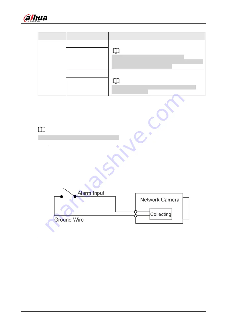
Connect alarm input device to the alarm input end of the I/O port. See Figure 1-2. 
Device collects different states of alarm input port when the input signal is idling and 
being grounded. 

  Device collects logic "1" when input signal is connected to +3V to +5V or idling. 

  Device collects logic "0" when input signal is grounded. 

Figure 1-2 Alarm input 


Step 2 

Connect alarm output device to the alarm output end of the I/O port. The alarm output is 
open-drain output, which works in the following modes. 

  Mode A: Level application. Alarm outputs high and low level, and the alarm outlet is OD, 

which requires external pull-up resistance (10K Ohm typical) to work. The maximum 
external pull-up level is 12V, maximum port current is 300mA and the default output 
signal is high-level (external pull-up voltage). The default output signal switches to low- 
level when there is alarm output (As long as the operating current is below 300mA, the 
output low-level voltage is lower than 0.8V). 

  Mode B: Switch application. Alarm output is used to drive external circuit, the 

maximum voltage is 12V and the maximum current is 300mA. If the voltage is higher 
than 12V, please use an additional electric relay. 

Содержание IPC-HDW3849H-AS-PV-0280B

Страница 1: ...Eyeball Network Camera Quick Start Guide ZHEJIANG DAHUA VISION TECHNOLOGY CO LTD V1 0 2...

Страница 2: ...he manual The manual would be updated according to the latest laws and regulations of related jurisdictions For detailed information refer to the paper manual CD ROM QR code or our official website If...

Страница 3: ...ion Transport use and store the device within the range of allowed humidity and temperature Heavy stress violent vibration or water splash are not allowed during transportation storage and installatio...

Страница 4: ...k device data and personal information by adopting measures which include but not limited to using strong password modifying password regularly upgrading firmware to the latest version and isolating c...

Страница 5: ...k Configuration 4 2 1 Initializing Device 4 2 2 Modifying Device IP Address 6 2 3 Logging in to Web Interface 6 3 Installation 8 3 1 Packing List 8 3 2 Dimensions 8 3 3 Installing Camera 8 3 3 1 Insta...

Страница 6: ...onents No Port name Description 1 Speaker Outputs audio 2 Power input Inputs 12V DC power Be sure to supply power as instructed in the manual Device abnormity or damage could occur if power is not sup...

Страница 7: ...Device collects logic 1 when input signal is connected to 3V to 5V or idling Device collects logic 0 when input signal is grounded Figure 1 2 Alarm input Step 2 Connect alarm output device to the ala...

Страница 8: ...arm input end of the I O port There will be high level and low level alarm signal generated by the alarm input device when alarm occurs set the input mode to NO default if the alarm input signal is lo...

Страница 9: ...nd the PC stays in the same network segment Plan usable network segment properly to connect the device to the network The following figures and interfaces are for reference only and the actual product...

Страница 10: ...ing Step 7 Set and confirm the password of the devices then enter a valid email address and then click Next The final setting interface is displayed Password can be modified or reset in System Setting...

Страница 11: ...therwise there will be wrong password notice Step 2 Select the devices whose IP addresses need to be modified and then click Modify IP The Modify IP Address interface is displayed Figure 2 3 Modify IP...

Страница 12: ...password in the login box and then click Login Step 3 For the first time login click Click Here to Download Plugin and then install the plugin as instructed The main interface is displayed when the i...

Страница 13: ...package The operation manual and related tool information are contained in the disk or the QR code and the actual package shall prevail Figure 3 1 Packing list 3 2 Dimensions Following figures are fo...

Страница 14: ...Quick Start Guide 9...

Страница 15: ...Quick Start Guide 10 Figure 3 3 Installation method 3 3 2 Installing SD Card Optional SD card slot is available on select models Disconnect the power before installing or removing the SD card...

Страница 16: ...Quick Start Guide 11 Figure 3 4 Installing SD card Press the reset button for 10 seconds to reset the device...

Страница 17: ...tart Guide 12 3 3 3 Attaching Camera Make sure that the mounting surface is strong enough to hold at least three times the weight of the device and bracket Figure 3 5 Cable going through the side cabl...

Страница 18: ...uide 13 Figure 3 6 Cable going through the mounting surface 3 3 4 Installing Waterproof Connector Optional This part is needed only when there is waterproof connector in the package and the device is...

Страница 19: ...Quick Start Guide 14 Figure 3 7 Installing waterproof connector 3 3 5 Adjusting Lens Angle...

Страница 20: ...Quick Start Guide 15 Figure 3 8 Adjusting lens angle...

Страница 21: ...Quick Start Guide...

Отзывы: